A 32-tap, linear-taper digital potentiometer acts as a variable resistor in a voltage divider, connected to the DIM input of an LED driver (operating as a PWM driver for the solenoid). The circuit drives solenoids ranging from 6V DC up to 40V DC, using only the solenoid's 6V to 40V DC source.
A similar version of this article appeared in the August 14, 2008 issue of ED magazine.
The proportional-control solenoids found in some industrial hydraulic systems are usually driven by microcontrollers or programmable logic controllers (PLCs). Such complex drivers typically require several different supply voltages for logic and control. (The purpose of proportional control is to move the solenoid plunger to an arbitrary position and leave it there.) A set-and-leave solenoid driver, however, should not require a costly PLC or the processing power of a μC. Ideally, it should operate from the solenoid's own supply voltage.
The circuit of Figure 1 meets these requirements while occupying only a small surface-mount footprint. U2 is a 350mA driver with built-in analog and PWM dimming control (MAX16804), normally used to drive high-brightness LEDs. In this application, its open-drain output (OUT) and current-sense terminal (CS+) connect directly to the solenoid terminals. Maximum solenoid current is set by R6. The circuit drives solenoids ranging from 6V DC up to 40V DC, using only the solenoid's 6V to 40V DC source. It was tested using a LEDex 24V pull-solenoid, rated for currents up to 290mA.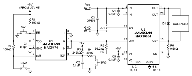
Figure 1. This small, surface-mount, digital-driver circuit provides proportional drive for a solenoid.
MAX5474, MAX5475 pdf datasheet:http://www.nxhydt.com/soft/39/2008/200810019475.html
U1 (MAX5474) is a 32-tap, nonvolatile, linear-taper digital potentiometer. Connected as a variable resistor, its internal 100kΩ variable resistor forms a divider with R5 to produce a 0V-to-3.17V analog voltage at U2's DIM input. After activating the potentiometer by depressing SW1 and setting the direction of change using SW2 (OPEN for up, CLOSED for down), you can increment this voltage with each toggle of SW3 (SW1 closed). Thirty-two steps are available, so 32 press-and-release cycles of SW3 traverses the range from 0V to 3.17V. Equation 1 gives the approximate voltage at DIM (VDIM) in terms of the wiper position:
where R5 = 56.2kΩ and N is the Nth wiper step (0 ≤ N ≤ 32). R3, R4, and C2 debounce the SW3 pulses that increment/decrement the wiper. Again, pressing SW1 enables wiper changes, and pressing SW2 (or not) controls the wiper's direction. U2 switches the solenoid at 200Hz, with a variable PWM duty cycle whose value depends on voltage at the DIM pin.
VDIM ≈ 5V((N - 1)3225.8Ω)/((N - 1)3225.8Ω + R5) (Eq. 1)
U2 is powered by the solenoid's power supply (24V in this case). U1 is powered by the V5 pin of U2, a 5V supply that can source as much as 2mA. Capacitors C1, C4, and C5 bypass the supply voltages at their respective IC pins. An optional bulk-holdup capacitor (C3) may be required if the circuit is located at a distance from the DC source.
To accommodate the PWM action applied by U2, freewheeling diode D1 allows current to circulate through the solenoid coil each time its power switches off (200 times per second). U2 provides indirect short-circuit and thermal protection to guard its output against overcurrent and short circuit conditions imposed by a defective solenoid or shorted leads. Jumper JU1 controls U2 by connecting its EN input (pin 19) to VIN (enable) or GND (disable). Table 1 summarizes conditions in the Figure 1 circuit for various positions of the solenoid.
Table 1. Solenoid-driver circuit data
| VIN (VRMS) | Solenoid travel (inches) | DIM pin voltage (VDC) | Solenoid pull-in current (mARMS) | Duty cycle (%) | Solenoid pull-out current (mARMS) |
| 24.00 | 0.4375 | 2.752 | 245 | 90.4 | 22.2 |
| 24.00 | 0.3125 | 2.424 | 221 | 76.1 | 10.6 |
| 24.00 | 0.25 | 1.991 | 143 | 64.3 | 10.3 |
| 24.00 | 0.1875 | 1.657 | 104.1 | 52.6 | 10.2 |
| 24.00 | 0.125 | 1.392 | 79.1 | 43.64 | 10.2 |
| 24.00 | 0.0625 | 1.083 | 48.6 | 32.8 | 10.2 |
| 24.00 | 0.0312 | 0.909 | 39.2 | 26.9 | 10.2 |
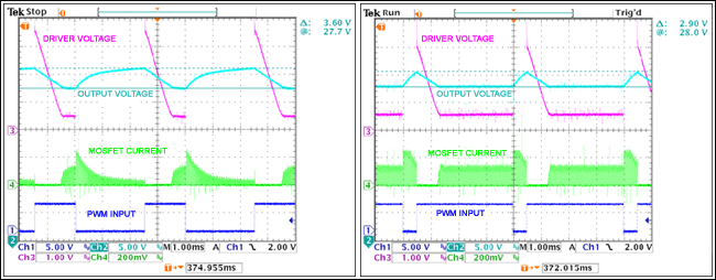
Figure 2 shows the solenoid-driver voltage and current pulses produced when the circuit operates at a 26% duty cycle. That duty cycle represents the solenoid voltage and 32.4mARMS current required to energize the solenoid coil and pull-in the solenoid plunger a distance of 0.0312in.
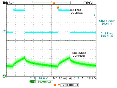
Figure 2. These voltage and current waveforms from the Figure 1 solenoid produce a plunger distance of 0.0312in for a 26% duty cycle and 0.3215in for a 76% duty cycle.
Figure 3 shows the solenoid-driver voltage and current pulses produced when the circuit operates at a 76% duty cycle. That duty cycle represents the solenoid voltage and 211mARMS current required to energize the solenoid coil and pull-in the solenoid plunger a distance of 0.312in.
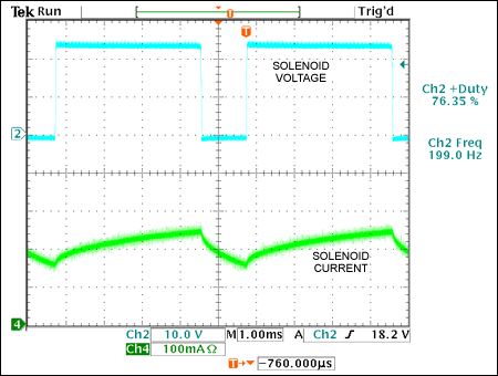
Figure 3. These solenoid voltage and current waveforms from the Figure 1 circuit produce a plunger distance of 0.31in.
 電子發燒友App





評論