lpc54102由于其性能和穩定性,在很多領域都有應用,下面我們來給大家分享一下lpc54102例程。
Nxp公司的LPC5410x系列產品是32位ARM Cortex-M4F/MO+MCU,集成了104KB SRAM,512KB閃存,3個12C,2個SPI,4個USART,32位計數器/定時器以及SCTimer/PWM和12位4.8MSPS ADC,具有低功耗,增強調試特性和高級支持區快等系統增強特性,適用于嵌入式應用。
LPC5410x為嵌入式應用的ARM cortexm4f基微控制器。這些設備包括一個可選的手臂Cortex-M0 +協處理器,104 KB的片上存儲器,512 KB芯片上的flash,五個通用定時器,一個State-Configurable計時器(SCTimer / PWM)PWM功能,一個RTC /報警定時器,一個24位多速率計時器(捷運),窗口看門狗定時器(WWDT),四個USARTs兩spi,三個Fast-modeplus i2c總線接口與高速奴隸模式,和一個12位4.8 Msamples / secADC。
LPC54102傳感器處理/運動解決方案主要特性:
a. 完整的硬件和軟件設計,準備定制
b. 32位LPC54102 Cortex-M4F / M0 +單片機
c. LPCXpresso54102發展局
d. 傳感器罩板
e. LPCOpen軟件驅動程序
f. LPC的傳感器融合框架
g. 博世BSX Lite傳感器融合庫
h. 軟件演示
i. 文檔
LPC54102傳感器處理/運動解決方案主要優勢:
a. 向你的應用程序添加6 -或9軸運動傳感器
b. 集成傳感器融合中間件和便攜式傳感器融合框架
c. 傳感器融合api允許用戶輕松地創建使用運動傳感器的應用程序
d. 額外的數字傳感器(壓力/溫度,環境光,接近)
e. 軟件開發工具,用于快速開始編寫、編譯和運行基于傳感器的應用程序
f. 為最終產品設計師提供一套豐富的參考設計材料,包括文檔、移植指南和示意圖
g. 可堆疊硬件支持更多的傳感器或添加插件模塊
h. 用于測量和原型的大量的pinouts
i. 低功率
LPC54102開發板介紹
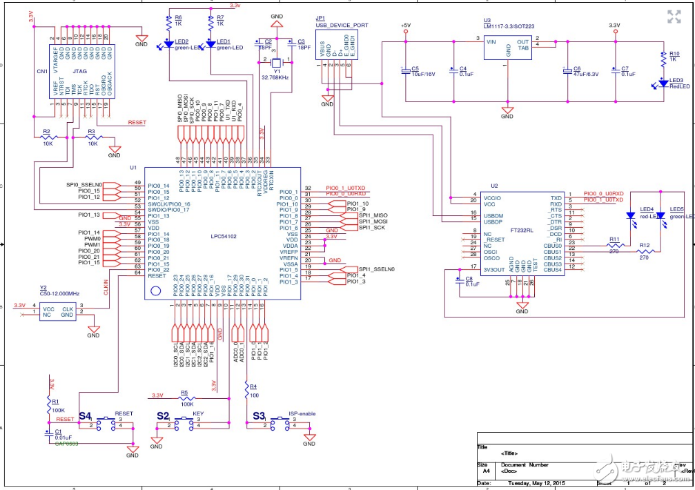
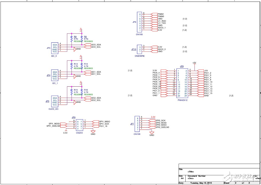
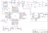
LPC54102開發板介紹原理圖
lpc54102例程:一
下面我們以萬利開發板的心率計應用筆記的LPC54102例程移植來做分析講解。
由于萬利開發板的不同設置,以及沒有PulseSensor傳感器,需要做一定的修改移植,使用萬利開發板上的AIN1作為模擬輸入,電位器的來回旋轉代表心跳的變化。
1、代碼修改
由于萬利開發板使用PIO1_4/AIN7作為電位器輸入,因此在初始化代碼中,做了如下修改:
其中在board.h中,取消了BOARD_NXP_LPCXPRESSO_54102的定義,而是重新定義了BOARD_MANLEY_LPC54102。
并在各個初始化代碼中,增加了針對萬利開發板的初始化代碼。
#if defined(BOARD_NXP_LPCXPRESSO_54102)
/* SEQ_A enables channels 0, 3 and 4; Uses software trigger; doesn‘t use BURST */
#define ADC_SEQ_A_CONFIG
TRIG_SOFT | /* Software trigger for SEQ_A */
TRIG_POL_POS | /* UM recommends this for S/W trigger */
MODE_EOS | /* Event generated after Sequence done */
ENABLE_CH(3) /* Associate channels 3 to SEQ_A */
#elif defined(BOARD_MANLEY_LPC54102)
#define ADC_SEQ_A_CONFIG
TRIG_SOFT | /* Software trigger for SEQ_A */
TRIG_POL_POS | /* UM recommends this for S/W trigger */
MODE_EOS | /* Event generated after Sequence done */
ENABLE_CH(7) /* Associate channels 7 to SEQ_A */
#endif // #if defined(BOARD_xxx)
static void ADC_PinMuxSetup(void)
{
#if defined(BOARD_NXP_LPCXPRESSO_54102)
/* All pins to inactive, neither pull-up nor pull-down. */
Chip_IOCON_PinMuxSet(LPC_IOCON, 1, 0, IOCON_MODE_INACT | IOCON_FUNC1 | IOCON_ANALOG_EN);
#elif defined(BOARD_MANLEY_LPC54102)
/* All pins to inactive, neither pull-up nor pull-down. */
Chip_IOCON_PinMuxSet(LPC_IOCON, 1, 4, IOCON_MODE_INACT | IOCON_FUNC1 | IOCON_ANALOG_EN);
#endif
}
2、運行
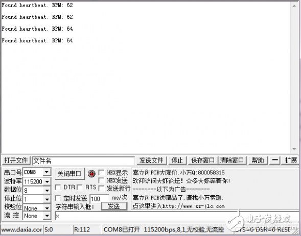
其余基本不變,下載后,將電位器來回旋轉,可以看到串口輸出了心跳數據。
3、代碼分析
該應用基本采用CM4初始化后即進入休眠。
CM0+核初始化ADC、Timer之后,進入休眠。
每秒20次喚醒后,采樣ADC,當采樣過半時,調用Compute_Heartrate算法計算是否產生心跳以及心跳間隔IBI。當發現后即輸出串口信息。
關鍵在于Compute_Heartrate算法,該算法采用PulseSensor官方的算法,基本是通過判斷ADC模擬量發現峰值、過半點等運算。
void Compute_Heartrate(void)
{
inti, N, Signal, runningTotal, current_sample = 0;
while(current_sample 《 SAMPLE_FREQUENCY/2){
Signal = temp_data[current_sample];
/* Keep track of time in milliseconds with sampleCounter variable */ sampleCounter = sampleCounter + 50;
/* Monitor the time since last beat to avoid noise */
N = sampleCounter - lastBeatTime;
/* Find the peak and trough of the pulse wave, avoid dichrotic noise by waiting 3/5 of last IBI */
if(Signal 《 thresh && N 》 (IBI/5)*3){
if (Signal 《 T){
/* Keep track of lowest point in pulse wave in the T variable */ T = Signal; } } /* Use threshold condition to filter out noise, store peak in P */ if(Signal 》 thresh && Signal 》 P){
P = Signal; } /* Analyze the data to find heartbeat */
f(N》500){
/* Avoid high frequency noise */
if((Signal》thresh)&&(Pulse==0)&&(N》(IBI/5)*3)){ Pulse=1; IBI=sampleCounter-lastBeatTime; lastBeatTime=sampleCounter; if(secondBeat){ secondBeat=0; for(i=0;i《=9;i++){ rate[i]=IBI; } } if(firstBeat){ firstBeat=0; secondBeat=1; continue; } /* Keep a running total of the last 10 IBI values */ runningTotal=0; for(i=0;i《=8;i++){ rate[i]=rate[i+1]; runningTotal += rate[i]; } /* Average the latest IBI values and calculate the BPM */ rate[9]=IBI; runningTotal+=rate[9]; runningTotal/=10; BPM=60000/runningTotal; QS=1; } }
/* Once the beat is over, reset values */
if (Signal 《 thresh && Pulse == 1){
Pulse = 0;
amp = P - T;
thresh = amp/2 + T;
P = thresh;
T = thresh; }
/* If we do not detect a heart beat in 2.5 seconds, reset all values */ if (N 》 2500){
thresh = 2548;
P = 2548;
T=2548; lastBeatTime= sampleCounter;
firstBeat = 1;
secondBeat = 0; } current_sample++; } }
lpc54102例程:二
LPCOpen_V2.14_LPC5410x的Peripheral例程
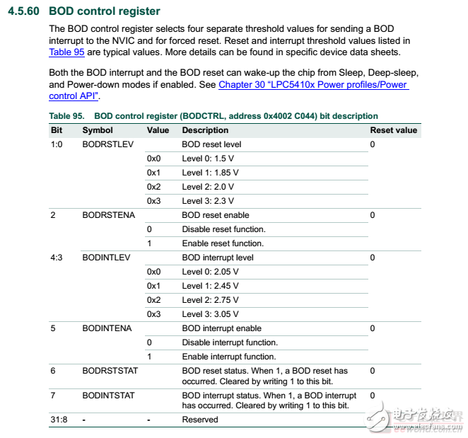
BOD是在設置了BOD中斷電壓水平(INTLEVEL),同時設置了重啟電壓水平(RSTLEVEL)之后,使能中斷與重啟,
源程序如下:
/* Set BOD detection interrupt to 3.05v and device reset to 1.5v */
Chip_PMU_SetBODLevels(PMU_BODRSTLVL_1_50V, PMU_BODINTVAL_3_05v);
/* Enable BOD reset and interrupt on low power level */
Chip_PMU_EnableBODReset();
Chip_PMU_EnableBODInt();
/* Enable BOD interrupt */
NVIC_EnableIRQ(BOD_IRQn);
為了方便觀察BOD中斷的運行,在中斷中設置Board_LED_Toggle需要修改如下:
/* Brown-out detector interrupt */
void BOD_IRQHandler(void)
{
/* Turn on LED */
for(int i = 0; i 《 1000; i++) {
Board_LED_Toggle(1);
}
}
最終運行效果要求正常運行LED是熄滅的,而掉電過程中BOD中斷使得LED閃亮,由于萬利的板子是低電平點亮LED,因此在初始化階段應該吧Board_LED_Set()的參數改為true,高電平之后LED熄滅。然后在BOD中斷中可以blink閃亮。

運行效果可以通過拔掉供電電源(本人的為JLINK直接給板子供電,在jlink commander中輸入Power off就可以)。此時LED會閃亮一下馬上熄滅(斷電)。
/**
* @brief PMU register block structure
* @note Most of the PMU support is handled by the PMU library.
*/
typedef struct {
__I uint32_t RESERVED0[4];
__I uint32_t RESERVED1[4];
__I uint32_t RESERVED2[4];
__I uint32_t RESERVED3[4];
__I uint32_t RESERVED4;
__IO uint32_t BODCTRL;
__I uint32_t RESERVED5;
__I uint32_t RESERVED6;
__IO uint32_t DPDWAKESRC;
} LPC_PMU_T;
#define LPC_PMU_BASE 0x4002C000UL
#define LPC_PMU ((LPC_PMU_T *) LPC_PMU_BASE)
(3)CLKOUT
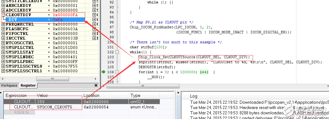
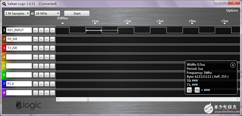
CLKOUT_DIV = 250
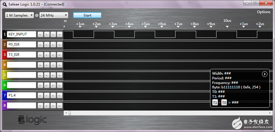
CPU被調試器暫停后,CLKOUT依然繼續輸出。
(4)CRC
CRC只需要運行例程即可。
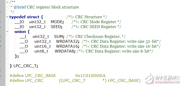
CRC的功能定義和代碼如下:

(5)IAP
IAP只需要運行例程即可。
在IDE中觀察memory,地址為0x00078000,可見在運行Chip_IAP_CopyRamToFlash前后的flash存儲內容發生了變化。

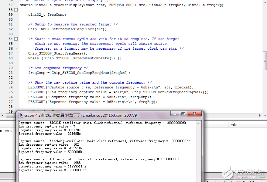
(6)FreqMeasure
只需要運行例程即可。
 電子發燒友App




評論