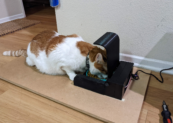
我設(shè)計(jì)并制造了這款自動(dòng)貓喂食器,以幫助我的糖尿病貓控制他的喂食并防止我的另一只貓吃他的食物。該喂食器可能對(duì)需要監(jiān)控寵物喂食需求的其他寵物主人有用。
我的貓需要藥食以及每日的胰島素劑量,他經(jīng)常會(huì)騙我們喂他兩次,或者另一只貓會(huì)吃他的食物,這讓我們很難知道他到底吃了多少。
我想創(chuàng)建一個(gè)封閉的喂食器,它可以檢測(cè)到哪只貓?jiān)谖故称魃希缓鬄檎_的貓打開。我的第一個(gè)想法是在他們的項(xiàng)圈上使用 NFC 標(biāo)簽,以便區(qū)分它們。然而,NFC 標(biāo)簽的有效接近是有問題的,因?yàn)樗鼈儍H在標(biāo)簽的幾毫米內(nèi)激活。經(jīng)過其他幾個(gè)想法,包括讀取它們背后的微芯片,我決定區(qū)分我的兩只貓的最簡(jiǎn)單方法是通過重量。
我在 Instructables 上找到了一個(gè)使用 Arduino Uno 創(chuàng)建浴室秤的項(xiàng)目,在成功構(gòu)建該項(xiàng)目后,我決定創(chuàng)建這個(gè)項(xiàng)目。秤精確到十分之一磅,但您的動(dòng)物會(huì)移動(dòng)很多,因此我們將嘗試區(qū)分大約半磅或四分之一公斤。
在確定這個(gè)解決方案之前,我創(chuàng)建了一個(gè)原型并經(jīng)歷了十幾個(gè)或更多的設(shè)計(jì)想法。
這是一個(gè)中等難度的項(xiàng)目。它需要使用一些基本的電動(dòng)工具、焊接、大量的 3D 打印、打磨和粘合。提供了項(xiàng)目的所有代碼以及如何修改代碼的說明。
補(bǔ)給品
所需工具:3D 打印機(jī)、電腦、鉆頭、烙鐵、螺絲刀套裝、鉗子、尖嘴鉗、砂紙、Dremel 工具(可選)、熱風(fēng)槍、氰基丙烯酸酯液體膠、鋼鋸、電壓表。
第 1 步:3D 打印
從稱重傳感器支架開始打印所有自定義組件。您將需要 4 個(gè)稱重傳感器底座和頂部。
第 2 步:計(jì)重秤構(gòu)建
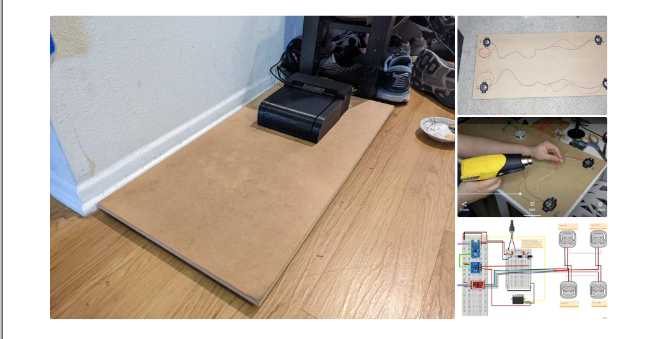
使用 MDF 等材料將您的體重秤底座切割成您喜歡的任何尺寸。我的是 30” x 15” (76cm x 38cm),進(jìn)紙器本身是 ~7” x 8.5” (18cm x 21.5cm)
使用稱重傳感器安裝座作為四個(gè)角的引導(dǎo)預(yù)鉆孔。標(biāo)出哪個(gè)稱重傳感器是哪個(gè)(左上角、左下角等)會(huì)很有幫助。
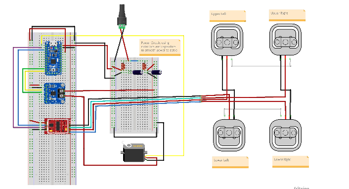
使用圖中的接線圖
1) 連接稱重傳感器線對(duì)
2)將電線剪成一定長度
3) 在使用剝線鉗拆下外殼并將線對(duì)絞在一起之前,將熱縮套管放在電線上。
將焊料涂在電線上,然后將熱縮管移到連接處并加熱。
連接線對(duì)后,您應(yīng)該有四根松散的紅線,每根線都來自一個(gè)稱重傳感器。您將使用四針母頭 RGB 接頭連接器。在左下稱重傳感器附近鉆一個(gè)足夠大的孔,以便電線穿過,其中紅色圓圈如上圖所示。接下來,按照?qǐng)D中的接線圖,將紅色電線焊接并熱縮到正確顏色的電線上RGB 母頭。您必須將正確的信號(hào)線連接到正確的顏色,否則您的秤將無法工作。將公連接器焊接到 HX711 上,這是接線圖中的紅色芯片,再次確保所有顏色的順序正確。還將 4 個(gè)分接引腳焊接到標(biāo)有 VCC、SCK、DT 和 GND 的孔上。
項(xiàng)目接線圖-點(diǎn)擊下載
第 3 步:秤校準(zhǔn)和測(cè)試
下一步,您將需要面包板、Arduino Uno 和一些跳線。
Sparkfun 有很棒的 Arduino 程序來運(yùn)行,最新版本可點(diǎn)擊鏈接在 GitHub 上找到
第一個(gè)軟件步驟是確定秤的校準(zhǔn)系數(shù)。為此,請(qǐng)運(yùn)行以下代碼:
|
/* Example using the SparkFun HX711 breakout board with a scale By: Nathan Seidle SparkFun Electronics Date: November 19th, 2014 License: This code is public domain but you buy me a beer if you use this and we meet someday (Beerware license). This is the calibration sketch. Use it to determine the calibration_factor that the main example uses. It also outputs the zero_factor useful for projects that have a permanent mass on the scale in between power cycles. Setup your scale and start the sketch WITHOUT a weight on the scale Once readings are displayed place the weight on the scale Press +/- or a/z to adjust the calibration_factor until the output readings match the known weight Use this calibration_factor on the example sketch This example assumes pounds (lbs). If you prefer kilograms, change the Serial.print(" lbs"); line to kg. The calibration factor will be significantly different but it will be linearly related to lbs (1 lbs = 0.453592 kg). Your calibration factor may be very positive or very negative. It all depends on the setup of your scale system and the direction the sensors deflect from zero state This example code uses bogde's excellent library:"https://github.com/bogde/HX711" bogde's library is released under a GNU GENERAL PUBLIC LICENSE Arduino pin 2 -> HX711 CLK 3 -> DOUT 5V -> VCC GND -> GND Most any pin on the Arduino Uno will be compatible with DOUT/CLK. The HX711 board can be powered from 2.7V to 5V so the Arduino 5V power should be fine. */ #include "HX711.h" #define LOADCELL_DOUT_PIN 3 #define LOADCELL_SCK_PIN 2 HX711 scale; float calibration_factor = -7050; //-7050 worked for my 440lb max scale setup void setup() { Serial.begin(9600); Serial.println("HX711 calibration sketch"); Serial.println("Remove all weight from scale"); Serial.println("After readings begin, place known weight on scale"); Serial.println("Press + or a to increase calibration factor"); Serial.println("Press - or z to decrease calibration factor"); scale.begin(LOADCELL_DOUT_PIN, LOADCELL_SCK_PIN); scale.set_scale(); scale.tare(); //Reset the scale to 0 long zero_factor = scale.read_average(); //Get a baseline reading Serial.print("Zero factor: "); //This can be used to remove the need to tare the scale. Useful in permanent scale projects. Serial.println(zero_factor); } void loop() { scale.set_scale(calibration_factor); //Adjust to this calibration factor Serial.print("Reading: "); Serial.print(scale.get_units(), 1); Serial.print(" lbs"); //Change this to kg and re-adjust the calibration factor if you follow SI units like a sane person Serial.print(" calibration_factor: "); Serial.print(calibration_factor); Serial.println(); if(Serial.available()) { char temp = Serial.read(); if(temp == '+' || temp == 'a') calibration_factor += 10; else if(temp == '-' || temp == 'z') calibration_factor -= 10; |
校準(zhǔn)秤后,您可以運(yùn)行此示例程序,然后將其修改為您自己的目的:
|
/* Example using the SparkFun HX711 breakout board with a scale By: Nathan Seidle SparkFun Electronics Date: November 19th, 2014 License: This code is public domain but you buy me a beer if you use this and we meet someday (Beerware license). This example demonstrates basic scale output. See the calibration sketch to get the calibration_factor for your specific load cell setup. This example code uses bogde's excellent library:"https://github.com/bogde/HX711" bogde's library is released under a GNU GENERAL PUBLIC LICENSE The HX711 does one thing well: read load cells. The breakout board is compatible with any wheat-stone bridge based load cell which should allow a user to measure everything from a few grams to tens of tons. Arduino pin 2 -> HX711 CLK 3 -> DAT 5V -> VCC GND -> GND The HX711 board can be powered from 2.7V to 5V so the Arduino 5V power should be fine. */ |
按照本項(xiàng)目中的比例校準(zhǔn)草圖中,獲取您的校準(zhǔn)因子 ex為-9660.0 ,您將在后面的步驟中需要用到這個(gè)數(shù)據(jù)。
第 4 步:進(jìn)紙器主體和蓋子組件
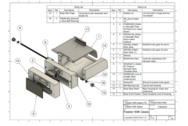
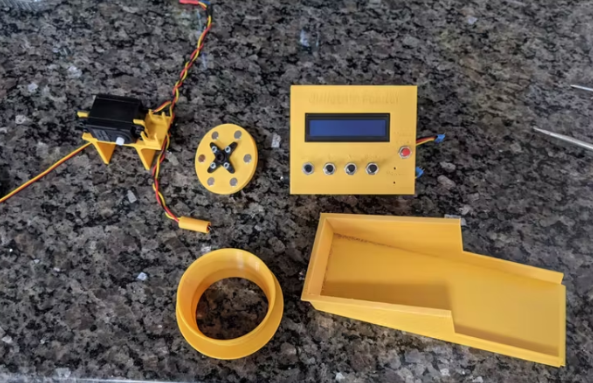
第一步是將進(jìn)紙器蓋連接到車身中間鉸鏈組件。您還需要塑料斜接齒輪軸、M5 連接螺母和 M5 螺紋桿。你要確保你的蓋子適合鉸鏈機(jī)構(gòu)的翅片之間并有間隙,沒有任何打嗝或擦傷。
確保您的連接螺母非常緊貼進(jìn)料器蓋上的六角連接器和塑料斜接齒輪。這里的舒適貼合非常重要,不應(yīng)該有任何玩耍。接下來,使用鋼鋸或 Dremel 上的圓形切割鉆頭將螺紋桿切割成 18 厘米。確保去除切割表面的任何毛刺。將螺桿穿過組件。您可能想先嘗試不使用連接螺母。如果桿無法插入或太緊,請(qǐng)小心地將孔鉆出合適的尺寸。
如果組件自由移動(dòng),則該檢查與進(jìn)料器主體前部的間隙。將車身前送紙器的定位方塊與車身中間鉸鏈對(duì)齊,確保兩個(gè)車身完全接觸,沒有間隙。配準(zhǔn)方格應(yīng)有助于防止錯(cuò)位 圖 6. 升高和降低蓋子以確保沒有間隙或配合問題。如果間隙看起來不錯(cuò),請(qǐng)從鉸鏈組件上拆下桿并暫時(shí)擱置這些組件。
您現(xiàn)在將車身中間鉸鏈粘到車身前端進(jìn)紙器上。在每個(gè)粘合表面的中心涂抹極少量的液體氰基丙烯酸酯膠(超級(jí)膠水)。我強(qiáng)烈建議在蠟紙上這樣做,因?yàn)槟拇蛴〖?huì)粘在它上面的表面上。將兩個(gè)組件牢牢按住并保持 30 秒。我們還可以將連接到 HX711 的桶形插頭和公頭 4 針 RGB 接頭粘到車身后電機(jī)上。
當(dāng)膠水固化時(shí),您將塑料斜接齒輪伺服連接到伺服。為此,您將在伺服系統(tǒng)上的冠狀齒輪的齒上加熱形成斜接齒輪。將烤箱預(yù)熱至華氏 160 度。取出烤盤,鋪上一層羊皮紙。將斜接齒輪放在羊皮紙上,然后將其放在烤箱的頂部架子上。PLA 的玻璃化轉(zhuǎn)變階段在 50-80 攝氏度之間。如果您使用的是 ABS 或其他塑料,請(qǐng)獲取該材料的玻璃化轉(zhuǎn)變溫度并相應(yīng)地更改烤箱溫度。當(dāng)您的烤箱完成預(yù)熱后,將斜接齒輪再放置大約三分鐘。將斜接齒輪從烤箱中取出,快速但小心地將齒輪上的孔對(duì)準(zhǔn)冠狀齒輪上方并用力按下。這一步要輕柔,因?yàn)樗芰犀F(xiàn)在變得柔韌且非常熱,并且容易變形。將斜接齒輪留在齒輪上,直到其冷卻,以避免熱收縮或膨脹。
冷卻后,用 M3 平頭螺栓和墊圈固定斜接齒輪。將伺服器放入車身后電機(jī)并用四個(gè) M5 x 30 螺栓固定。
車身中間鉸鏈和車身前饋線現(xiàn)在粘合在一起,用饋線蓋、六角螺母、斜接齒輪和 M5 桿重新組裝鉸鏈機(jī)構(gòu)。將兩個(gè)軸承放入軸承蓋并將軸承蓋安裝到車身中鉸鏈的孔中。您現(xiàn)在應(yīng)該已組裝好所有 3D 組件,除了齒輪的護(hù)罩和電子設(shè)備的門。
第 5 步:電子組裝
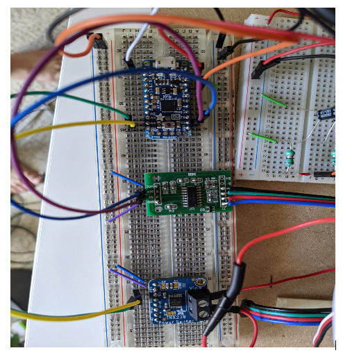
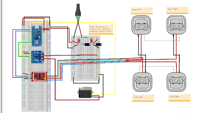
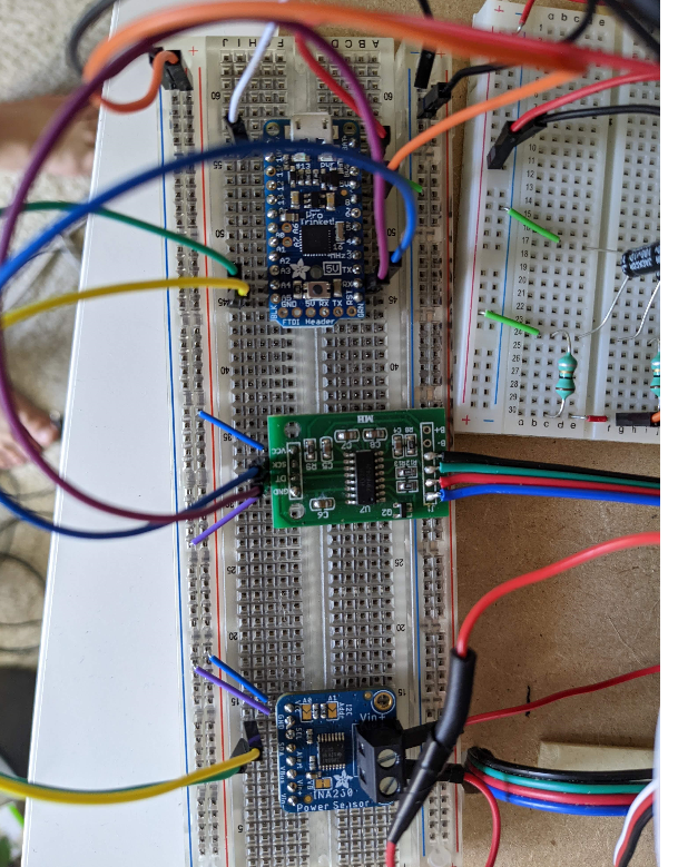
在這個(gè)階段,我們將在面包板上組裝電子設(shè)備,以確保我們所有的電子元件都按預(yù)期運(yùn)行。按照?qǐng)D中搭建電源電路,但不要連接舵機(jī)的黃色信號(hào)線。電路的左側(cè)是 Arduino 的電源,電路的右側(cè)是伺服的電源。伺服系統(tǒng)的電源也通過 Adafruit INA260 電流和電壓感應(yīng)芯片運(yùn)行,該芯片將充當(dāng)我們的安全系統(tǒng)。如果您對(duì)組件通電時(shí)的電壓正確感到滿意,請(qǐng)完成芯片的接線,確保連接公頭和母頭 RGB 接頭,這會(huì)將您的秤連接到進(jìn)紙器。
第 6 步:編碼和測(cè)試
/**
Developed for Hobbyiest use by Tomas Diaz-Wahl for Kalliot LLC.
Copyright ? 2022 Kalliot LLC
Redistribution and use in source and binary forms, with or without modification, are permitted provided that the following
conditions are met:
1. Redistributions of source code and documentation must retain the above copyright notice, this list of conditions and the
following disclaimer.
2. Redistributions in binary form must reproduce the above copyright notice, this list of conditions and the following
disclaimer in the documentation and/or other materials provided with the distribution.
3. Neither the name of the copyright holder nor the names of its contributors may be used to endorse or promote products
derived from this software without specific prior written permission.
THIS SOFTWARE AND DOCUMENTATION ARE PROVIDED BY THE COPYRIGHT HOLDERS AND CONTRIBUTORS "AS IS" AND ANY EXPRESS OR IMPLIED WARRANTIES,
INCLUDING, BUT NOT LIMITED TO, THE IMPLIED WARRANTIES OF MERCHANTABILITY AND FITNESS FOR A PARTICULAR PURPOSE ARE
DISCLAIMED. IN NO EVENT SHALL THE COPYRIGHT HOLDER OR CONTRIBUTORS BE LIABLE FOR ANY DIRECT, INDIRECT, INCIDENTAL,
SPECIAL, EXEMPLARY, OR CONSEQUENTIAL DAMAGES (INCLUDING, BUT NOT LIMITED TO, PROCUREMENT OF SUBSTITUTE GOODS OR SERVICES;
LOSS OF USE, DATA, OR PROFITS; OR BUSINESS INTERRUPTION) HOWEVER CAUSED AND ON ANY THEORY OF LIABILITY, WHETHER IN CONTRACT,
STRICT LIABILITY, OR TORT (INCLUDING NEGLIGENCE OR OTHERWISE) ARISING IN ANY WAY OUT OF THE USE OF THIS SOFTWARE,
EVEN IF ADVISED OF THE POSSIBILITY OF SUCH DAMAGE.
**/
/*
* This project uses two third-party libraries.
* INA260 and HX711 libraries can be found at:
*
*
*/
#include
#include
#include "HX711.h"
Adafruit_INA260 ina260 = Adafruit_INA260();
Servo servo;
HX711 scale;
/*
* Debug class is designed to output info to the serial monitor, (found under the tools menu in the Arduino IDE),
* This is designed to make sure that all boards and electronics are working as designed.
* TO ACTIVATE DEBUG CLASS MAKE SURE debugOn IS SET TO TRUE.
*/
class Debug {
public:
static const bool debugOn = false; //turn debug on and off
void printMsg(int x){
if (debugOn){
Serial.print(x);
Serial.flush();
}
}
void printMsg(String x){
if (debugOn){
Serial.print(x);
Serial.flush();
}
}
void printLine(int x){
if (debugOn){
Serial.println(x);
Serial.flush();
}
}
void printLine(String x){
if (debugOn){
Serial.println(x);
Serial.flush();
}
}
void setUpSerial(){
if (debugOn){
Serial.begin(9600);
// Wait until serial port is opened
while (!Serial) { delay(10); }
}
}
};//Debug
/*
* Queue class is designed to make a basic queue for our current measurements.
* There is no need to modify this class.
*/
class Queue{
private:
const static int maxQueueSize = 8;
float arr [maxQueueSize];
int queuePos;
public:
Queue(){
for (int i = 0; i < maxQueueSize; i++)
{
arr[i] = 0;
}
queuePos = maxQueueSize - 1;
}// Queue constructor
int enqueue (float val){
queuePos += 1;
if (queuePos >= maxQueueSize){
queuePos = 0;
}
arr[queuePos] = val;
}
float getAvg (){
float total = 0;
float avg;
for (int i = 0; i < maxQueueSize; i++){
total += arr [i];
}
avg = total / maxQueueSize;
return avg;
}
};// class Queue
/*
* Feeder class allows for motion of the feeder lid as well as implementing a check
* to see if there is an obstruction affecting lid motion.
* You will need to change several variable in the private data section of this class.
* You MUST change: calibrationFactor, minCatWeight, maxCatWeight
* You MAY need to change: maxCurrent, lidMaxPosition, any pin designations you wish to change.
*/
class Feeder {
public:
const int moveAmount = 1; // How much the servo should move per command
/*
* Set up stores an known initial position in the microcontroller memory.
* Tells the microcontroller which pin the servo is on.
* Activates and sets the scale calibration factor (see SparkFun_HX711_Calibration sketch)
*/
void setUp () {
servo.write (initialPos);
servo.attach(servoPin);
delay (1000);
scale.begin(LOADCELL_DOUT_PIN, LOADCELL_SCK_PIN);
scale.set_scale(calibrationFactor); //This value is obtained by using the SparkFun_HX711_Calibration sketch
}
/*
* reset should be called when powering up the feeder but can be called manually as well.
* reset tares the scale as well as moves the servo to a known position and then slowly moves the servo to position 0.
*/
void reset () {
scale.tare(); //Assuming there is no weight on the scale at start up, reset the scale to 0
servo.write (initialPos);
delay (500);
for (int i = initialPos; i > lidMinPosition; i--){
servo.write (i);
delay (servoDelay);
}
pos = lidMinPosition;
numberOfRetries = 0;
}
bool IsCatOn ()
{
float weight = scale.get_units();
return ((weight >= minCatWeight) && (weight <= maxCatWeight));
}
void moveServo (int amount){
pos += amount;
servo.write(pos);
}
void raiseLid (int amount){
moveServo(amount);
}
void lowerLid (int amount){
moveServo (-amount);
}
/*
* Open and close lid are nearly identical in function (haha! get it? they're actually methods)
* These methods are designed to use the Adafruit INA260 current sensor to detect the current during operation.
* If the current draw from the servo is too high, it may indicate an obstruction.
* The implementation of this is a little complex so I recommend not messing with these values.
*/
float openLid () {
while ((pos < lidMaxPosition) && (numberOfRetries < maxRetriesAllowed))
{
raiseLid(moveAmount);
float current = ina260.readCurrent();
myQueue.enqueue(current);
if (myQueue.getAvg() >= maxCurrent){
numberOfRetries += 1;
lowerLid(5);
delay(1000);//Wait before lid open retry
debug.printLine("Max Current Detected, Closing Lid Before Retry");
if(numberOfRetries > maxRetriesAllowed){
exit (-1);//Lid is blocked
}
closeLid();
return;
}
delay(servoDelay);
} // end while loop
numberOfRetries = 0;//reset counter
} // openLid
void closeLid (){
while (pos > lidMinPosition)
{
lowerLid(moveAmount);
float current = ina260.readCurrent();
myQueue.enqueue(current);
if (myQueue.getAvg() >= maxCurrent){
numberOfRetries += 1;
raiseLid(5);
delay(1000);
debug.printLine("Max Current Detected, Opening Lid Before Retry");
if(numberOfRetries > maxRetriesAllowed){
exit (-1);//Lid is blocked
}
openLid();
return;
}
delay(servoDelay);
} // end while loop
numberOfRetries = 0; //reset retry counter
} // CloseLid
private:
const float calibrationFactor = -9660.0; //This value is obtained using the SparkFun_HX711_Calibration sketch.
const int LOADCELL_DOUT_PIN = 10;
const int LOADCELL_SCK_PIN = 11;
const int servoDelay = 40; // Speed of servo. (change not recommended)
const int initialPos = 20; // initial position of servo when feeder is reset. Be careful!; servo will move at max speed to this position.
const int lidMaxPosition = 70; // Maximum position of servo may vary depending on tolerances.
const int lidMinPosition = 0;
const int servoPin = 9;
const float minCatWeight = 11.0; // lbs. Set the minimum activation weight of your animal.
const float maxCatWeight = 1000.0; // lbs. Set the maximum weight of animal. (if you have a bigger dog or cat you dont want getting into the feeder)
const float maxCurrent = 250.00; // Maximum current that is allowed under normal feed operation. Triggers overcurrent protection mechanism.
const int maxRetriesAllowed = 10; // Maximum number of lid movement commands during overcurrent protection before lid operation ceases.
const int numberOfMeasurements = 5; // Number of current measurements to be averaged.
int pos;
int numberOfRetries;
Queue myQueue;
Debug debug;
}; // Feeder
Feeder feeder;
Debug debug;
void setup() {
delay(1000); //wait for boot up
// DEBUG BEGIN
debug.setUpSerial(); // Enables serial port communication. (Make sure debugOn set to true in debug class for USB serial communication)
debug.printLine("Adafruit INA260 Test");
if (!ina260.begin()) {
debug.printLine("Couldn't find INA260 chip");
exit (-1);
}
debug.printLine("Found INA260 chip");
debug.printLine("Configuring Ina");
debug.printMsg("INA260_TIME_8_244_ms = ");
debug.printLine(INA260_TIME_8_244_ms);
ina260.setCurrentConversionTime(INA260_TIME_8_244_ms); // Changes the measurement interval. This makes current readings less spikey.
debug.printMsg("INA260_COUNT_4 = ");
debug.printLine(INA260_COUNT_4);
ina260.setAveragingCount(INA260_COUNT_4); // Changes the number of measurements averaged by the INA260 sensor. This will also make readings less spikey.
INA260_ConversionTime convTime = ina260.getCurrentConversionTime(); // Verifying Ina Configuration
INA260_AveragingCount avgCount = ina260.getAveragingCount(); // Verifying Ina Configuration
if (convTime != INA260_TIME_8_244_ms){
exit(-1);
}
if (avgCount != INA260_COUNT_4){
exit(-1);
}
debug.printLine("Configured Ina");
// DEBUG END
feeder.setUp(); // initialize feeder.
feeder.reset(); // set feeder lid to position 0 and tare scale.
delay(2000);// During construction of the feeder, this delay can be set much higher to align the servo gear with the door gear. (avoid pinchy fingies)
}
void loop() {
debug.printLine("I'm in the loop");
// The following code was used during construction for debug purposes
// feeder.openLid();
// feeder.closeLid();
//debug.printLine("Program Exit");
//
// exit(0);
//END DEBUG
//main code for feeder operation
if (feeder.IsCatOn()) {
feeder.openLid();
}
else{ // Cat is not on the feeder
feeder.closeLid();
}
delay(1000);
}
現(xiàn)在一切都已連接好,您可以繼續(xù)應(yīng)用代碼。通過插入電源來打開電路。使用 USB 電纜將您的 Arduino 或 Pro Trinket 連接到計(jì)算機(jī)。始終確保在連接到計(jì)算機(jī)時(shí)為您的電路供電,否則伺服器可能會(huì)嘗試通過信號(hào)線獲取電力,這可能會(huì)損壞我們的組件。您可能希望暫時(shí)斷開伺服的信號(hào)線。將提供的代碼復(fù)制到 Arduino IDE 中的新草圖中并保存。確保將 INA260 庫添加到 IDE。默認(rèn)情況下應(yīng)該包含伺服庫,并且您應(yīng)該在校準(zhǔn)秤時(shí)添加了 HX711 庫。此項(xiàng)目需要包含所有三個(gè)庫。
1) 通過轉(zhuǎn)到調(diào)試類并將 debugOn 設(shè)置為 true 來打開調(diào)試模式。
2)進(jìn)入Feeder類,進(jìn)入底部的私有數(shù)據(jù)部分。
3) 將calibrationFactor 更改為您在刻度校準(zhǔn)步驟中獲得的值,并確保添加一位小數(shù)。
4) 將 minCatWeight 更改為比您的寵物的重量小一點(diǎn)。
5) 暫時(shí)不要更改 maxCatWeight。
6) 如果您使用的引腳名稱與接線圖中的引腳名稱不同,您可以在本節(jié)中進(jìn)行設(shè)置。
7)編譯并將草圖上傳到您的Arduino。
8)在Arduino IDE中打開串口監(jiān)視器,確保找到INA260芯片。
9)然后它應(yīng)該一遍又一遍地打印出“我在循環(huán)中”。
10) 返回調(diào)試類并將 debugOn 設(shè)置為 false。
11)連接舵機(jī)的信號(hào)線并重新上傳草圖。
12) 舵機(jī)應(yīng)旋轉(zhuǎn)到 20 度,然后緩慢旋轉(zhuǎn)回零。
13) 斷開 USB 和電源。
14)我們現(xiàn)在知道伺服的位置為零。對(duì)齊伺服和軸的斜接齒輪,并將四個(gè)緊固件添加到角落,小心不要弄臟任何電線。蓋子應(yīng)該完全關(guān)閉,沒有間隙。
15) 重新連接饋線的電源。蓋子應(yīng)迅速升至 20 度,然后慢慢接近零。這是校準(zhǔn)階段,每次饋線通電時(shí)都會(huì)發(fā)生。
16) 把一些重量放在秤上,看著它打開。
17) 確保在卸下重量時(shí)它關(guān)閉。
18) 您可以通過阻止蓋子移動(dòng)來測(cè)試安全功能。(如果安全功能失效,請(qǐng)謹(jǐn)慎使用)
如果您的喂食器工作正常,是時(shí)候進(jìn)入最后的步驟了。
使用雙面膠帶或 Velcro 將完成的進(jìn)料器安裝到秤上。
將 maxCatWeight 設(shè)置為比您的寵物的重量稍大一點(diǎn),然后重新上傳草圖,但這次是您的 Pro Trinket。確保面包板一切正常。我們將通過將所有東西都轉(zhuǎn)移到焊盤上來最小化電子設(shè)備的尺寸。使用與圖 4 之前相同的接線圖,將每個(gè)組件添加到焊接板上。組件的確切布置無關(guān)緊要,只要連接與接線圖中的相同。您可以復(fù)制圖 10 中的排列。圖 11 顯示了如何使用焊料橋接連接。
將焊盤安裝到電子支架上,并使用雙面膠帶或 Velcro 將其固定在送料器內(nèi)。
為了不安裝覆蓋齒輪的護(hù)罩,蓋子必須完全打開。將蓋子滑入到位并關(guān)閉蓋子。在頂部放置固定螺釘以將護(hù)罩固定到位。
我們將饋線插入到 Govee 智能插頭中,這樣我們就可以使用智能揚(yáng)聲器對(duì)其進(jìn)行控制。
-
nfc
+關(guān)注
關(guān)注
59文章
1617瀏覽量
180405 -
喂食器
+關(guān)注
關(guān)注
1文章
23瀏覽量
3054
發(fā)布評(píng)論請(qǐng)先 登錄
相關(guān)推薦
基于單片機(jī)的寵物定時(shí)自動(dòng)喂食器設(shè)計(jì)(原理圖&程序)
怎么實(shí)現(xiàn)寵物自動(dòng)喂食器的設(shè)計(jì)?
自制一個(gè)寵物喂食器
寵物定時(shí)喂食器設(shè)計(jì)資料
如何科學(xué)喂養(yǎng)愛寵?用螢石智能可視寵物喂食器
智能寵物喂食器越來越受到喜歡養(yǎng)寵物的人青睞
制作一個(gè)易于使用的自動(dòng)寵物喂食器
基于物聯(lián)網(wǎng)的寵物喂食器
基于WTR096-28SS芯片方案的寵物喂食器實(shí)現(xiàn)智能化喂食功能


 設(shè)計(jì)一個(gè)寵物NFC定時(shí)喂食器


評(píng)論