串口原理圖
串口1咱們已經用作rtt的print使用了,所以使用另外一組串口來進行串口的教程,這里一定要注意下,alios的這個板子原理圖是有點問題的,標注的是串口3PA2和PA3,實際上小飛哥調了好久,最后萬用表量引腳才發現是原理圖標注錯誤,實際上是UART4,PA0和PA1
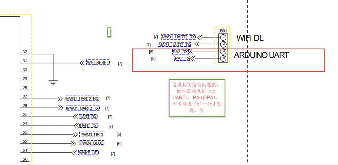
cubemx中引腳選擇預配置
選擇PA0、PA1,配置為串口模式,波特率什么的見圖示: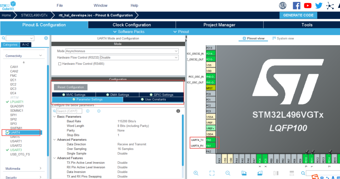
開啟中斷,優先級可以根據自己的需求配置,本次不使用DMA,所以DMA就先不進行配置了
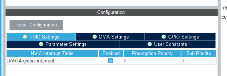
配置是非常簡單的,就不多啰嗦了,配置完直接生成代碼就OK了
HAL庫串口代碼詳解
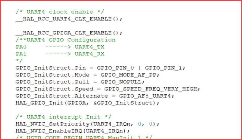
cubemx里面配置了一大堆,生成的應用代碼主要在初始化中:
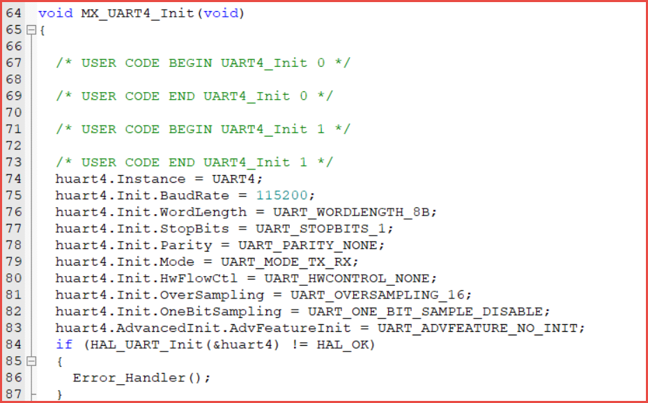
關于串口的接口是很多的,本次主要使用3個接口,發送、接收和接收回調
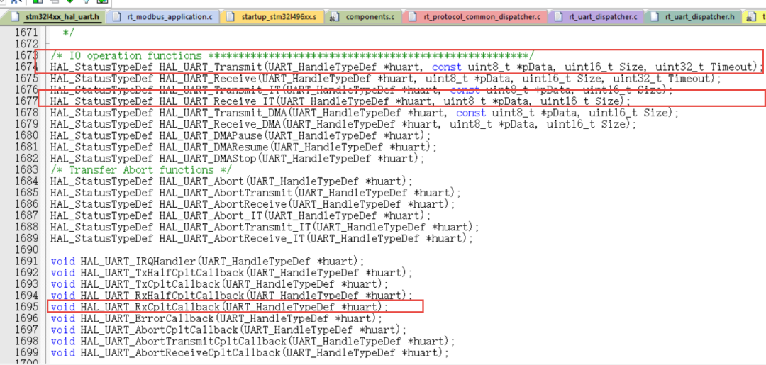
HAL庫數據接收的設計思想是底層配置完成后,暴露給用戶的是一組回調函數,用戶不用關心底層實現,只需要關注應用層邏輯即可,回調函數是定義為_weak屬性的接口,用戶可以在應用層實現
/**
*@briefRxTransfercompletedcallback.
*@paramhuartUARThandle.
*@retvalNone
*/
__weakvoidHAL_UART_RxCpltCallback(UART_HandleTypeDef*huart)
{
/*Preventunusedargument(s)compilationwarning*/
UNUSED(huart);

/*NOTE:Thisfunctionshouldnotbemodified,whenthecallbackisneeded,
theHAL_UART_RxCpltCallbackcanbeimplementedintheuserfile.
*/
}
發送也有對應的callback,我們只需要在callback處理我們的邏輯即可。
串口收發設計
教程不玩虛的,本章節小飛哥從實際應用出發,通過解析協議數據,順便講解uart的收發設計。
1、串口接收:
先來看看HAL庫串口接收的接口函數,這就是使用庫函數的好處,底層實現不用關心,只要會用接口就行了
/**
*@briefReceiveanamountofdataininterruptmode.
*@noteWhenUARTparityisnotenabled(PCE=0),andWordLengthisconfiguredto9bits(M1-M0=01),
*thereceiveddataishandledasasetofu16.Inthiscase,Sizemustindicatethenumber
*ofu16availablethroughpData.
*@paramhuartUARThandle.
*@parampDataPointertodatabuffer(u8oru16dataelements).
*@paramSizeAmountofdataelements(u8oru16)tobereceived.
*@retvalHALstatus
*/
HAL_StatusTypeDefHAL_UART_Receive_IT(UART_HandleTypeDef*huart,uint8_t*pData,uint16_tSize);
如何使用這個接口接收數據呢?
從接口描述可以看到,第1個參數是我們的串口號,第2個參數數我們用于接收數據的buffer,第3個參數是數據長度,即要接受的數據量,這里我們每次僅接收一個數據即進入邏輯處理
每次取一個數據,放到rxdata的變量中
HAL_UART_Receive_IT(&huart4,&rxdata,1);
HAL庫所有的串口是共享一個回調函數的,那么如何區分數據是來自哪一個串口的?這個邏輯可以在應用實現,區分不同的串口號,根據對應的串口號實現對應的邏輯即可
voidHAL_UART_RxCpltCallback(UART_HandleTypeDef*huart)
{

if(huart->Instance==UART4)
{
//rt_sem_release(sem_uart_rec);
embedded_set_uart_rec_flag(RT_TRUE);
embedded_set_uart_timeout_cnt(0);
HAL_UART_Receive_IT(&huart4,&rxdata,1);
mb_process_frame(rxdata,CHANNEL_MODBUS);
}
}
2、數據幀接收完成判斷
通訊基本上都是不定長數據的接收,一般對于一個完整的通訊幀來說,是有長度字段的,分以下幾種接收完成判斷方式
特殊數據格式,比如結束符,像正點原子串口教程的“回車、換行(0x0D,0x0A)”
數據長度,適用已知數據長度的數據幀,根據接收到的數據長度跟數據幀里面的長度是否一致,判斷接受是否完成
超時判斷,定時器設計一個超時機制,一定時間內沒有數據進來即認為數據傳輸結束
空閑中斷,串口是有個空閑中斷的,這個實現類似于超時機制
也可以從軟件設計實現,比如設計一個隊列,取數據即可,隊列中沒數據即認為數據接受完成
方式有很多,本章節主要使用數據長度和定時器超時兩種方式來講解
3、串口發送
串口發送比較簡單,先來看看發送接口函數,類似接收函數,只需要把我們的數據放進發送buffer,啟動發送即可
/**
*@briefSendanamountofdatainblockingmode.
*@noteWhenUARTparityisnotenabled(PCE=0),andWordLengthisconfiguredto9bits(M1-M0=01),
*thesentdataishandledasasetofu16.Inthiscase,Sizemustindicatethenumber
*ofu16providedthroughpData.
*@noteWhenFIFOmodeisenabled,writingadataintheTDRregisteraddsone
*datatotheTXFIFO.WriteoperationstotheTDRregisterareperformed
*whenTXFNFflagisset.Fromhardwareperspective,TXFNFflagand
*TXEaremappedonthesamebit-field.
*@paramhuartUARThandle.
*@parampDataPointertodatabuffer(u8oru16dataelements).
*@paramSizeAmountofdataelements(u8oru16)tobesent.
*@paramTimeoutTimeoutduration.
*@retvalHALstatus
*/
HAL_StatusTypeDefHAL_UART_Transmit(UART_HandleTypeDef*huart,constuint8_t*pData,uint16_tSize,uint32_tTimeout);
數據接收及協議幀解析設計
數據接收:
基于數據長度和超時時間完成數據幀發送完成的判斷:
定時器中斷回調設計,實現邏輯為,當收到串口數據時,開始計時,超過100ms無數據進來,認為數據幀結束,同時釋放數據接收完成的信號量,接收到接受完成的信號量之后,重置一些數據,為下一次接收做好準備
voidHAL_TIM_PeriodElapsedCallback(TIM_HandleTypeDef*htim)
{
if(htim->Instance==TIM15)
{
//if(RT_EOK==rt_sem_take(sem_uart_rec,RT_WAITING_NO))
//{
if(embedded_get_uart_rec_flag())
{
/*100ms超時無數據接收*/
if(embedded_get_uart_timeout_cnt()>9)
{
embedded_set_uart_rec_flag(RT_FALSE);

rt_sem_release(sem_uart_timeout);
}
}

//}
}
}
串口回調設計:
串口回調要實現的邏輯比較簡單,主要是數據接收、解析:
voidHAL_UART_RxCpltCallback(UART_HandleTypeDef*huart)
{
if(huart->Instance==UART4)
{
//rt_sem_release(sem_uart_rec);
embedded_set_uart_rec_flag(RT_TRUE);
embedded_set_uart_timeout_cnt(0);
HAL_UART_Receive_IT(&huart4,&rxdata,1);
process_frame(rxdata,CHANNEL_UART4);
}
}
/協議架構/
/數據頭(2字節)+數據長度(2字節,不包含數據頭)+功能碼+數據+校驗碼(CRC16-MODBUS)/
我們采用這個協議框架來解析數據,數據解析可以設計成一個簡單的狀態機,根據每一步決定下一步做什么
比如針對上面的協議,我們就可以分幾步設計:
1、解析數據頭1;
2、解析數據頭2;
3、解析數據長度;
4、接收數據;
5、校驗數據CRC;
6、調用命令回調函數;
把握好這個步驟,設計其實非常簡單
先來定義一個簡單的枚舉,表示每一個狀態:
typedefenum
{
STATUS_HEAD1=0,
STATUS_HEAD2,
STATUS_LEN,
STATUS_HANDLE_PROCESS
}frame_status_e;
然后封裝數據解析函數:
/*協議架構*/
/**數據頭(1字節)+數據長度(2字節,不包含數據頭)+功能碼+數據+校驗碼(CRC16-MODBUS)**/
#definePROTOCOL_HEAD10x5A
#definePROTOCOL_HEAD20xA5
intprocess_frame(constuint8_tdata,constuint8_tchannel)
{
uint16_tcrc=0;
uint16_tlen=0;
staticframe_status_eframe_status;
staticuint16_tindex=0;
/*timeoutresetthereceivestatus*/
if(RT_EOK==rt_sem_take(sem_uart_timeout,RT_WAITING_NO))
{
index=0;
frame_status=STATUS_HEAD1;
}
switch(frame_status)
{
caseSTATUS_HEAD1:
if(data==PROTOCOL_HEAD1)
{
frame_status=STATUS_HEAD2;
buffer[index++]=data;
}
else
{
frame_status=STATUS_HEAD1;
index=0;
}
break;
caseSTATUS_HEAD2:
if(data==PROTOCOL_HEAD2)
{
frame_status=STATUS_LEN;
buffer[index++]=data;
}
else
{
frame_status=STATUS_HEAD1;
index=0;
}
break;
caseSTATUS_LEN:
if(data>=0&&data<=?MAX_DATA_LEN)
????????{
????????????frame_status?=?STATUS_HANDLE_PROCESS;
????????????buffer[index++]?=?data;
????????}
????????else
????????{
????????????frame_status?=?STATUS_HEAD1;
????????????index?=?0;
????????}
????????break;
????case?STATUS_HANDLE_PROCESS:
????????buffer[index++]?=?data;
????????len?=?buffer[LEN_POS];
????????if?(index?-?3?==?len)
????????{
????????????crc?=?embedded_mbcrc16(buffer,?index?-?2);
????????????if?(crc?==?(buffer[index?-?1]?|?buffer[index?-?2]?<
對用的功能函數:
我們采用 attribute at機制的方式,將我們的回調函數注冊進去:
typedefvoid(*uart_dispatcher_func_t)(constuint32_t,constuint8_t*,constuint32_t);
typedefstructuart_dispatcher_item
{
union
{
struct
{
uint8_tchannel;
uint8_tcmd_id;
};
uint32_tmagic_number;
};
uart_dispatcher_func_tfunction;
}uart_dispatcher_item_t;
#defineUART_DISPATCHER_CALLBACK_REGISTER(ch,id,fn)staticconstuart_dispatcher_item_tuart_dis_table_##ch##_##id
__attribute__((section("uart_dispatcher_table"),__used__,aligned(sizeof(void*))))=
{.channel=ch,.cmd_id=id,.function=fn}
intcall_reg_cb(uint8_t*frame,uint8_tdata_len,intchannel,uint8_tcmd_id);
回調函數:
這樣設計可以把驅動層,協議解析層和應用層完全分開,用戶只需要注冊相關的命令,實現回調即可,完全不用關心底層實現
voiddispatcher_on_02_callback(constuint32_tchannel,constuint8_t*data,constuint32_tdata_len)
{
constchar*str="func02isrunning
";
uart_write((uint8_t*)str,rt_strlen(str),100);
rt_kprintf("func02isrunning
");
}
UART_DISPATCHER_CALLBACK_REGISTER(1,0x02,dispatcher_on_02_callback);
voiddispatcher_on_03_callback(constuint32_tchannel,constuint8_t*data,constuint32_tdata_len)
{
constchar*str="func03isrunning
";
uart_write((uint8_t*)str,rt_strlen(str),100);
rt_kprintf("func03isrunning
");
}
UART_DISPATCHER_CALLBACK_REGISTER(1,0x03,dispatcher_on_03_callback);
voiddispatcher_on_04_callback(constuint32_tchannel,constuint8_t*data,constuint32_tdata_len)
{
constchar*str="func04isrunning
";
uart_write((uint8_t*)str,rt_strlen(str),100);
rt_kprintf("func04isrunning
");
}
UART_DISPATCHER_CALLBACK_REGISTER(1,0x04,dispatcher_on_04_callback);
voiddispatcher_on_05_callback(constuint32_tchannel,constuint8_t*data,constuint32_tdata_len)
{
rt_kprintf("func05isrunning
");
}
UART_DISPATCHER_CALLBACK_REGISTER(1,0x05,dispatcher_on_05_callback);
voiddispatcher_on_06_callback(constuint32_tchannel,constuint8_t*data,constuint32_tdata_len)
{
rt_kprintf("func06isrunning
");
}
UART_DISPATCHER_CALLBACK_REGISTER(1,0x06,dispatcher_on_06_callback);
測試效果
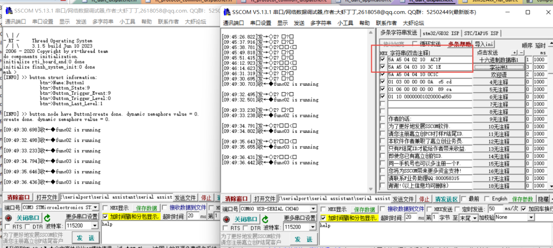
通過上面的回調函數注冊,我們來測試下是不是達到預期情況:
審核編輯:劉清
-
定時器
+關注
關注
23文章
3241瀏覽量
114486 -
RTT
+關注
關注
0文章
65瀏覽量
17088 -
UART接口
+關注
關注
0文章
124瀏覽量
15268 -
HAL庫
+關注
關注
1文章
114瀏覽量
6177
原文標題:04-HAL庫UART配置及協議解析設計
文章出處:【微信號:小飛哥玩嵌入式,微信公眾號:小飛哥玩嵌入式】歡迎添加關注!文章轉載請注明出處。
發布評論請先 登錄
相關推薦
stm32 HAL庫UART中斷 使用說明
STM32 HAL庫 CUBEMX配置 ADC采集 精選資料分享
【STM32的HAL庫開發】CubeMX配置HAL庫,不進串口中斷的問題 精選資料分享
串口通信小試牛刀~使用STM32CubeMX+ HAL庫點亮流水燈

【STM32 HAL】UART串口通訊

STM32 HAL庫 CubeMX教程(五)串口通信基礎

STM32 HAL庫 CUBEMX配置 ADC采集

STM32串口通信HAL庫配置中 UART_IT_xx與UART_FLAG_xx 的區別


 HAL庫UART在cubemx中的配置


評論