背景
使用的開發板為大疆的 RoboMaster-C 型開發板,基礎工程為 rt-thread>bsp>stm32f407-robomaster-c
BMI088模塊開發
BMI088 為 robomaster-c 開發板上集成的6軸imu,在此為提高速度陀螺儀和加速度計均使用使用 SPI 通訊方式,
首先將飛控程序中針對 RT-Thread 的 SPI 設備驅動封裝的 SPI 讀寫函數借鑒過來:
#define SPI_DIR_READ 0x80
#define SPI_DIR_WRITE 0x00
/**
This function write a 8 bit reg.
@param device the SPI device attached to SPI bus
@param reg Register address
@param val The value to be written
@return RT_EOK if write successfully.
/
rt_inline rt_err_t spi_write_reg8(rt_device_t spi_device, uint8_t reg, uint8_t val)
{
uint8_t buffer[2];
rt_size_t w_byte;
buffer[0] = SPI_DIR_WRITE | reg;
buffer[1] = val;
w_byte = rt_spi_transfer((struct rt_spi_device )spi_device, buffer, NULL, 2);
return (w_byte == 2) ? RT_EOK : RT_ERROR;
}
/**
This function read a 8 bit reg.
@param device the SPI device attached to SPI bus
@param reg Register address
@param buffer Buffer of read data
@return RT_EOK if read successfully.
/
rt_inline rt_err_t spi_read_reg8(rt_device_t spi_device, uint8_t reg, uint8_t buffer)
{
uint8_t reg_addr;
reg_addr = SPI_DIR_READ | reg;
return rt_spi_send_then_recv((struct rt_spi_device*)spi_device, (void*)?_addr, 1, (void*)buffer, 1);
}
/**
This function read multiple contiguous 8 bit regs.
@param device the SPI device attached to SPI bus
@param reg Start register address
@param buffer Buffer of read data
@param len The number of read registers
@return RT_EOK if read successfully.
/
rt_inline rt_err_t spi_read_multi_reg8(rt_device_t spi_device, uint8_t reg, uint8_t buffer, uint8_t len)
{
uint8_t reg_addr;
reg_addr = SPI_DIR_READ | reg;
return rt_spi_send_then_recv((struct rt_spi_device*)spi_device, (void*)?_addr, 1, (void*)buffer, len);
}
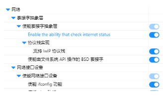
因為C板上 STM32 與 BMI088 是通過 SPI1 相連接,Kconfig 文件中添加 SPI1 部分并使能,并且需要進入到CubeMX 中使能 SPI1,這一步最重要的是選取引腳,這樣 RTT 中的 SPI1 設備驅動才能使用:
BMI088 驅動
主要就是先對 BMI088 上的陀螺儀和加速度計分別進行初始化,設置相關采樣參數,需要注意的一點是加速度計上電后默認是 I2C 模式,需要其片選引腳上檢測到電平后才會切換為 SPI 模式并保持,如果沒有正確處理這一步可能會導致這個現象:上電后讀不出來加速度計,reset 后又能讀取。
static rt_err_t accelerometer_init(void)
{
uint8_t accel_id;
/* init spi bus /
rt_device_open(accel_spi_dev, RT_DEVICE_OFLAG_RDWR);
/ dummy read to let accel enter SPI mode /
spi_read_reg8(accel_spi_dev, BMI088_ACC_BGW_CHIPID, &accel_id);
rt_hw_us_delay(1000);
spi_read_reg8(accel_spi_dev, BMI088_ACC_BGW_CHIPID, &accel_id);
/ read accel id /
spi_read_reg8(accel_spi_dev, BMI088_ACC_BGW_CHIPID, &accel_id);
if (accel_id != BMI088_ACC_BGW_CHIPID_VALUE) {
LOG_W("Warning: not found BMI088 accel id: %02x", accel_id);
return RT_ERROR;
}
/ soft reset /
spi_write_reg8(accel_spi_dev, BMI088_ACC_SOFTRESET, 0xB6);
rt_hw_us_delay(2000);
/ dummy read to let accel enter SPI mode /
spi_read_reg8(accel_spi_dev, BMI088_ACC_BGW_CHIPID, &accel_id);
/ enter normal mode /
spi_write_reg8(accel_spi_dev, BMI088_ACC_PWR_CTRL, 0x04);
rt_hw_us_delay(55000);
/ set default range and bandwidth /
accel_set_range(6); / 6g /
accel_set_sample_rate(800); / 800Hz sample rate /
accel_set_bwp_odr(280); / Normal BW /
/ enter active mode /
spi_write_reg8(accel_spi_dev, BMI088_ACC_PWR_CONF, 0x00);
rt_hw_us_delay(1000);
return RT_EOK;
}
static rt_err_t gyroscope_init(void)
{
uint8_t gyro_id;
/ init spi bus /
rt_device_open(gyro_spi_dev, RT_DEVICE_OFLAG_RDWR);
spi_read_reg8(gyro_spi_dev, BMI088_CHIP_ID_ADDR, &gyro_id);
if (gyro_id != BMI088_GRRO_CHIP_ID) {
LOG_W("Warning: not found BMI088 gyro id: %02x", gyro_id);
return RT_ERROR;
}
/ soft reset /
spi_write_reg8(gyro_spi_dev, BMI088_BGW_SOFT_RST_ADDR, 0xB6);
rt_hw_us_delay(35000); // > 30ms delay
gyro_set_range(2000); / 2000dps /
gyro_set_sample_rate(2000); / OSR 2000KHz, Filter BW: 230Hz /
/ enable gyroscope /
__modify_reg(gyro_spi_dev, BMI088_MODE_LPM1_ADDR, REG_VAL(0, BIT(7) | BIT(5))); / {0; 0} NORMAL mode */
rt_hw_us_delay(1000);
return RT_EOK;
}
這里為了減小陀螺儀的零飄影響,可以對陀螺儀進行校準,得出補償的值。
static void bmi088_calibrate(void){
static float start_time;
static uint16_t cali_times = 5000; // 需要足夠多的數據才能得到有效陀螺儀零偏校準結果
float accel[3], gyro[3];
float gyroMax[3], gyroMin[3];
float gNormTemp, gNormMax, gNormMin;
static float gyroDiff[3], gNormDiff;
int16_t acc_raw[3];
start_time = dwt_get_time_s();
do
{
if (dwt_get_time_s() - start_time > 20)
{
// 校準超時
gyro_offset[0] = GxOFFSET;
gyro_offset[1] = GyOFFSET;
gyro_offset[2] = GzOFFSET;
bmi088_g_norm = gNORM;
break;
}
dwt_delay_s(0.005);
// 開始時先置零,避免對數據讀取造成影響
bmi088_g_norm = 0;
gyro_offset[0] = 0;
gyro_offset[1] = 0;
gyro_offset[2] = 0;
for (uint16_t i = 0; i < cali_times; i++)
{
accel_read_raw(acc_raw);
accel[0] = accel_range_scale * acc_raw[0];
accel[1] = accel_range_scale * acc_raw[1];
accel[2] = accel_range_scale * acc_raw[2];
gNormTemp = sqrtf(accel[0] * accel[0] +
accel[1] * accel[1] +
accel[2] * accel[2]);
bmi088_g_norm += gNormTemp;
gyro_read_rad(gyro);
for(uint8_t j = 0; j < 3; j++){
gyro_offset[j] += gyro[j];
}
// 記錄數據極差
if (i == 0)
{
gNormMax = gNormTemp;
gNormMin = gNormTemp;
for (uint8_t j = 0; j < 3; j++)
{
gyroMax[j] = gyro[j];
gyroMin[j] = gyro[j];
}
}
else
{
if (gNormTemp > gNormMax)
gNormMax = gNormTemp;
if (gNormTemp < gNormMin)
gNormMin = gNormTemp;
for (uint8_t j = 0; j < 3; j++)
{
if (gyro[j] > gyroMax[j])
gyroMax[j] = gyro[j];
if (gyro[j] < gyroMin[j])
gyroMin[j] = gyro[j];
}
}
// 數據差異過大認為收到外界干擾,需重新校準
gNormDiff = gNormMax - gNormMin;
for (uint8_t j = 0; j < 3; j++)
gyroDiff[j] = gyroMax[j] - gyroMin[j];
if (gNormDiff > 0.6f ||
gyroDiff[0] > 1.0f ||
gyroDiff[1] > 1.0f ||
gyroDiff[2] > 1.0f)
break;
LOG_I("gyroDiff: %f",gNormDiff);
for(uint8_t j = 0; j < 3; j++){
LOG_D("gyroDiff%d: %f",j ,gyroDiff[j]);
}
dwt_delay_s(0.0005);
}
// 取平均值得到標定結果
bmi088_g_norm /= (float)cali_times;
LOG_W("bmi088_g_norm: %f",bmi088_g_norm);
for (uint8_t i = 0; i < 3; i++)
{
gyro_offset[i] /= (float)cali_times;
LOG_W("gyro_offset: %f",gyro_offset[i]);
}
cali_count++;
} while (gNormDiff > 0.3f ||
fabsf(bmi088_g_norm - 9.8f) > 0.5f ||
gyroDiff[0] > 1.0f ||
gyroDiff[1] > 1.0f ||
gyroDiff[2] > 1.0f ||
fabsf(gyro_offset[0]) > 0.01f ||
fabsf(gyro_offset[1]) > 0.01f ||
fabsf(gyro_offset[2]) > 0.01f);
// 根據標定結果校準加速度計標度因數
accel_scale = 9.81f / bmi088_g_norm;
}
由于校準時間較長,并且需要處于穩定的環境下,定期或更換開發板時進行一次校準即可,校準成功后手動修改 GxOFFSET 等宏;通過在 menuconfig 中使能 BSP_BMI088_CALI 進行校準;在串口終端可以查看校準進度,如多次校準失敗,適當調大誤差范圍。
抽象設備
為提高程序的模塊化,選用不同傳感器時的靈活性,將 bmi088 抽象為 imu一類設備,抽象出 imu_init 、 gyro_read 、 gyro_config、accel_read、accel_config、temp_read 6個操作方法。
struct imu_ops{
rt_err_t (*imu_init)(void);
rt_err_t (*gyro_read)(float data[3]);
rt_err_t (*gyro_config)(struct gyro_configure cfg);
rt_err_t (*accel_read)(float data[3]);
rt_err_t (*accel_config)(struct accel_configure cfg);
float (*temp_read)(void);
};
項目選用不同的磁力計傳感器時,對接這些個接口即可,以 bmi088 為例:
struct imu_ops imu_ops = {
.imu_init = bmi088_init,
.gyro_read = bim088_gyro_read,
.gyro_config = bim088_gyro_config,
.accel_read = bim088_accel_read,
.accel_config = bim088_accel_config,
.temp_read = bmi088_temp_read,
};
應用層需要使用磁力計時,調用 imu_ops 中的操作方法即可:
/* read data /
float gyro[3],acc[3],temp;
imu_ops.gyro_read(gyro);
imu_ops.accel_read(acc);
temp = imu_ops.temp_read();
/ config */
struct gyro_configure usr_conf_g = GYRO_CONFIG_DEFAULT;
struct acc_configure usr_conf_a = ACCEL_CONFIG_DEFAULT;
到此就可以使用imu模塊獲取傳感器原始數據啦。
存在問題及優化方向
目前為了提高性能,imu設備的注冊對接形式是比較簡陋的;
目前對 imu 設備的抽象只考慮到6軸 imu;
需要注意陀螺儀校準處理部分。
-
傳感器
+關注
關注
2548文章
50698瀏覽量
752053 -
驅動器
+關注
關注
52文章
8164瀏覽量
146033 -
加速度計
+關注
關注
6文章
699瀏覽量
45860 -
STM32F407
+關注
關注
15文章
187瀏覽量
29376 -
RT-Thread
+關注
關注
31文章
1273瀏覽量
39926
發布評論請先 登錄
相關推薦
基于RT-Thread的RoboMaster電控框架設計
RT-Thread編程指南
RT-Thread全球技術大會:RT-Thread上的單元測試框架與運行測試用例


 基于RT-Thread的RoboMaster電控框架(三)


評論