九CN032套件中的新功率板的連接方式說明
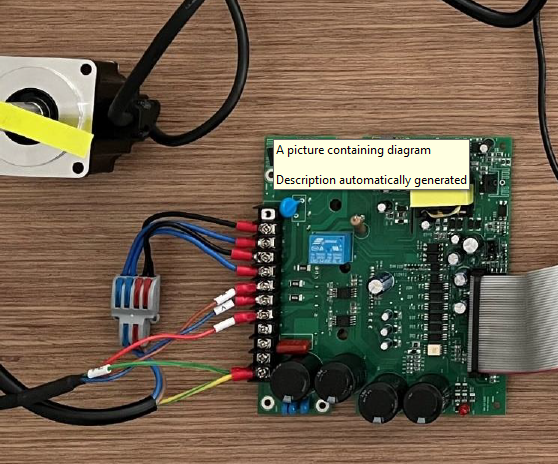
老版本功率板:
新版本功率板:
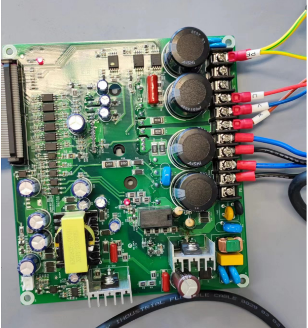
差別
新的版本從PE保護地起,中間是2個接線柱,老版本是3個,注意千萬不要按照老的接線方式,會炸管子。
另外,請注意
1220V限制1A
3下電后放電徹底后再操作

十IAR新工程的創建示例
請參考百度網盤與客戶的培訓視頻
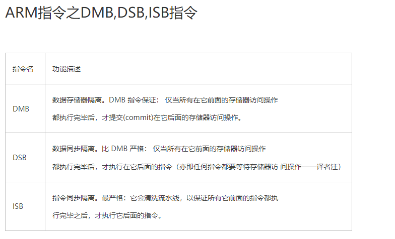
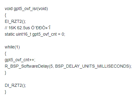
十一如何開啟中斷嵌套
在中斷函數進入后插入
__asm volatile ("cpsie i");//打開全局中斷
__asm volatile ("isb");//同步指令
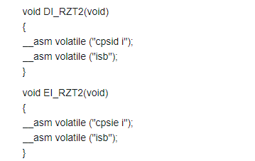
出中斷處插入關閉中斷
__asm volatile ("cpsid i");//
__asm volatile ("isb");//同步指令
示例
十二EVK xSPI0 IAR編譯及燒寫程序說明
1CN8接2-3,接通QSPI的電源
2Smart configurator選擇xspi0啟動
3Debugger可以選擇I-jet或者J-Link
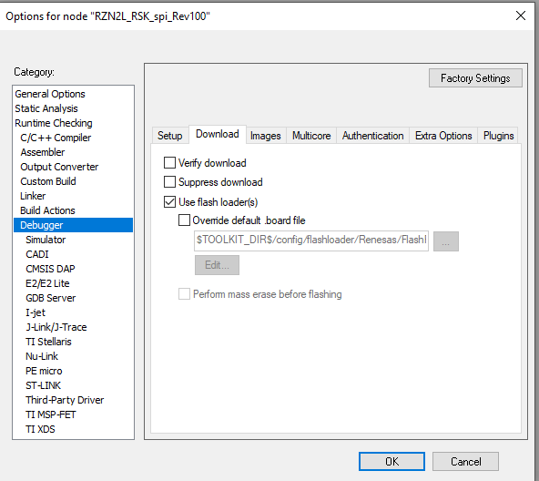
4I-jet需配置如下
5斷點設置如下
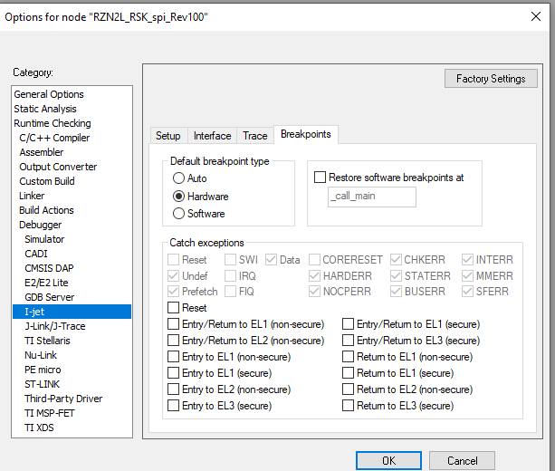
如使用J-Link也使用硬件斷點
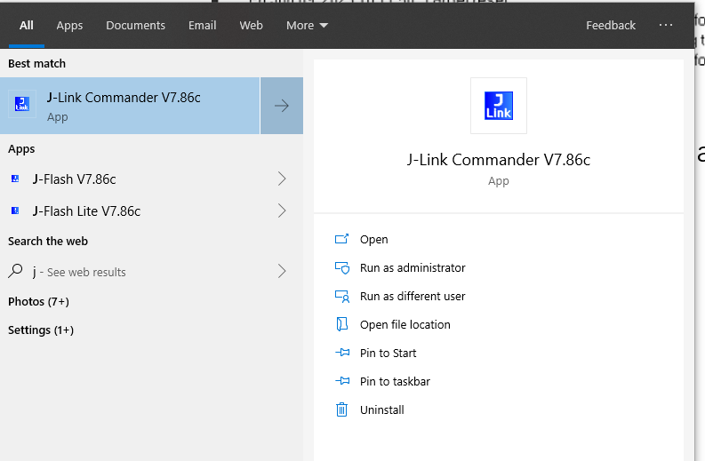
如出現類似如下錯誤報警:xspi0地址區域驗證錯誤

需使用J-Link commander擦除qspi flash
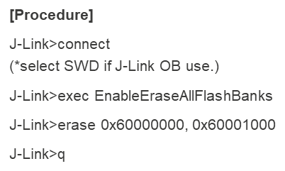
如下部分代碼加在
case USB_STATUS_REQUEST: /* Receive Class Request */
里

==3代表上位機串口軟件打開,可以進行數據收發。
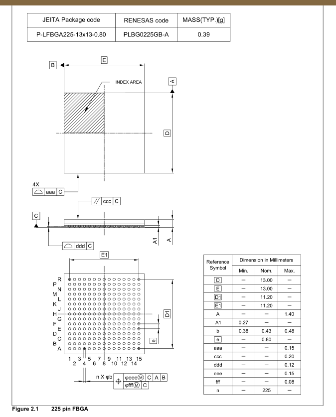
十四關于N2L 225pin封裝
1可以直接使用CN032的主板封裝(autium designer格式)
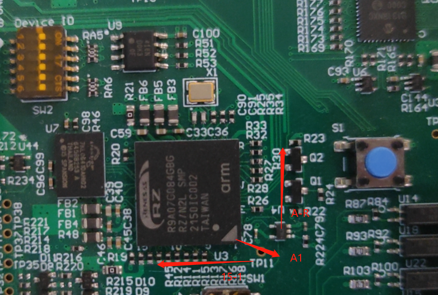
2參考datasheet時候,其視圖為底視圖,即球面對人
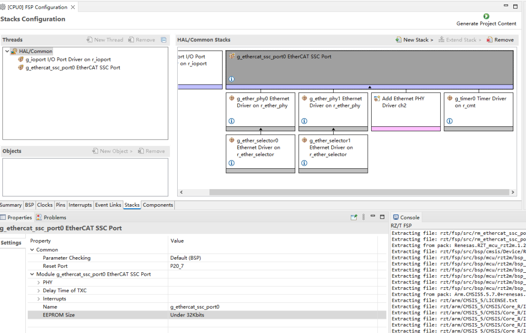
把eeprom size改成與RSK板子對照
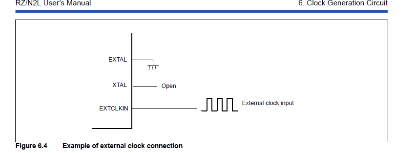
十六外部晶振推薦使用有源晶振
十七
P17_5 使用注意
初始狀態是RSTOUT配置,不要用做Digital output.
使用CS2. CS3不能單獨使用
十九EIP例程測試
需要下載CODESYS version 3.5.15.10 32-bit,因為例程和這個版本適配,其他版本不行。
CODESYS Development System V3

下載前需要先注冊codesys會員,免費。
二十T2M N2L電流環運行時間測試
可以在CN032套件上測試,在電流環運行前后增加GPIO翻轉,然后去除掉反轉時間就是電流環運行時間:
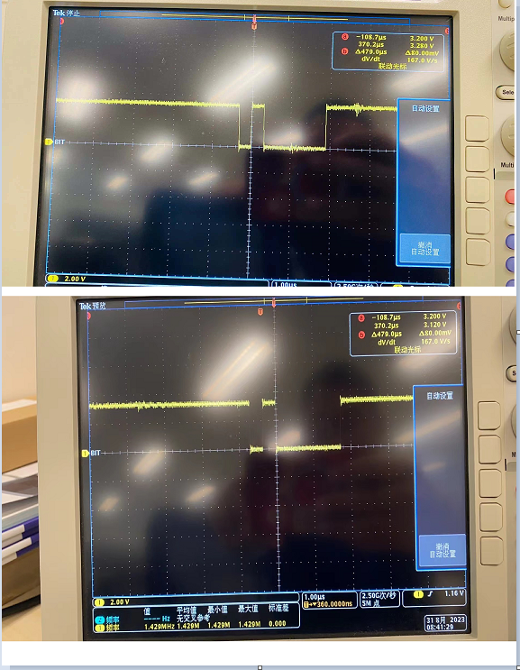
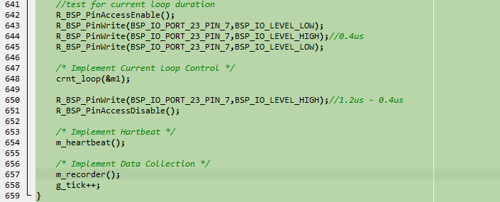
從圖上看,T2M電流環大約1us N2L 1.35us.
二十一Freertos使用指導
使用freertos和多個不同優先級中斷時候,需要修改如下內容:
1Target File: port.c
左右滑動查看完整內容
void vApplicationIRQHandler (uint32_t ulICCIAR)
{
 #if 0
  /* Re-enable interrupts. */
  __asm("cpsie i");
 #endif
 bsp_common_interrupt_handler(ulICCIAR);
}
2Target File: bsp_irq.c
左右滑動查看完整內容
void bsp_common_interrupt_handler (uint32_t id)
{
 uint16_t gic_intid;
 /* Get interruot ID (GIC INTID). */
 gic_intid = (uint16_t) (id & BSP_PRV_ID_MASK);
#if VECTOR_DATA_IRQ_COUNT > 0
 if (BSP_CORTEX_VECTOR_TABLE_ENTRIES <= gic_intid)
 ?{
 ? ?/* Remain the interrupt number */
 ? ?g_current_interrupt_num[g_current_interrupt_pointer++] =
 ? ?(uint16_t) (gic_intid - BSP_CORTEX_VECTOR_TABLE_ENTRIES);
 ? ?__asm volatile ("dmb");
 ? ?#if 1
 ? ? ?/* Enable nested interrupt. */
 ? ? ?__asm volatile ("cpsie i");
 ? ? ?__asm volatile ("isb");
 ? ? ?#endif
 ? ? ?/* Branch to an interrupt handler. */
 ? ? ?g_vector_table[(gic_intid - BSP_CORTEX_VECTOR_TABLE_ENTRIES)]();
 ? ? ?}
 ? ? ?else
 ? ?#endif
{
/* Remain the interrupt number */
g_current_interrupt_num[g_current_interrupt_pointer++] = gic_intid;
__asm volatile ("dmb");
#if 1
/* Enable nested interrupt. */
__asm volatile ("cpsie i");
__asm volatile ("isb");
#endif
/* Branch to an interrupt handler. */
g_sgi_ppi_vector_table[gic_intid]();
}
#if 1
/* Disable nested interrupt. */
__asm volatile ("cpsid i");
__asm volatile ("isb");
#endif
g_current_interrupt_pointer--;
}
二十二FSP更改設置后編譯報錯
bsp_mcu_device_pn_cfg.h :No such file or direction
問題一般發生在
Changed from RSK+RZN2L (RAM execution without flash memory) to RZN2L Custom User Board (xSPI0 x1 boot mode)
bsp_mcu_device_pn_cfg.h 沒有自動生成,所以報錯:

Workaround:
Please create a new project to change the board setting to RZN2L Custom User Board.
二十三MTU3定時器中斷進不去中斷問題(FSP V1.2以下版本,1.2和以上無問題)
1增加三相電機驅動
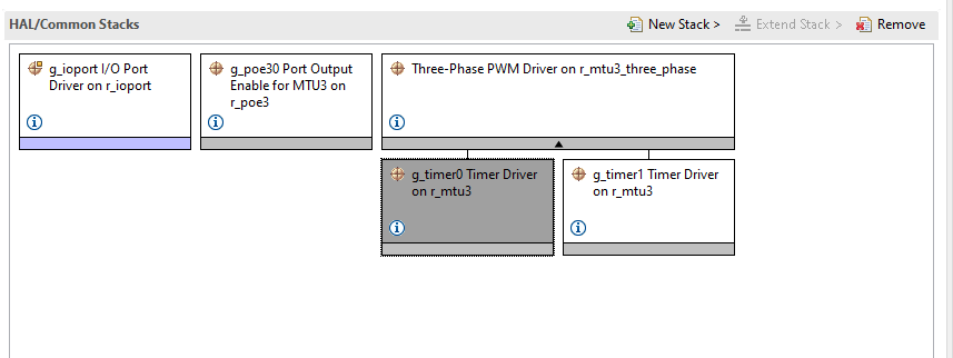
2配置定時器中斷(定時器比較匹配中斷,一般在這個中斷里更新pwm duty cycle)
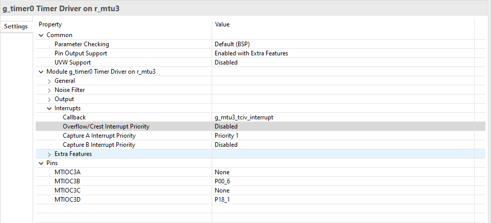
此時不用管報錯:
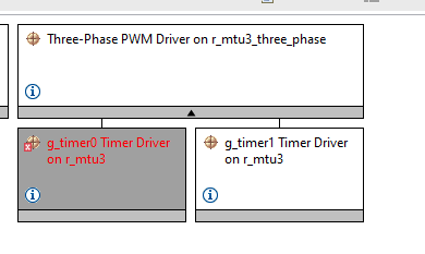
直接點生成代碼

3修改如下生成的文件
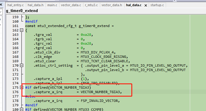
4增加中斷回調函數

5舉一反三,如果其他定時器中斷進不去,也可以查查是不是hal_data.c里面生成的代碼中斷向量號這里宏定義出錯了。
二十四串口引腳使用注意
串口引腳最好定義在P16 P18這兩組引腳上,因為這兩組支持ELC,可以方便的去做不定長數據的接收。
審核編輯:湯梓紅
-
主板
+關注
關注
53文章
1836瀏覽量
70480 -
瑞薩
+關注
關注
34文章
22290瀏覽量
86066 -
中斷
+關注
關注
5文章
895瀏覽量
41391 -
DC電源
+關注
關注
0文章
221瀏覽量
15806
原文標題:RZ/T2M RZ/N2L RZ/T2L系列應用心得(6-下)
文章出處:【微信號:瑞薩MCU小百科,微信公眾號:瑞薩MCU小百科】歡迎添加關注!文章轉載請注明出處。
發布評論請先 登錄
相關推薦
瑞薩教你如何使用RZ/T2L RZ/N2L RSK J-Link OB

RZ/T2M 組 RZ/T2M Motor Solution Kit Startup 手冊(for RZ/T2M Motion Control Utility)

RZ/T2M 組 RZ/T2M Motor Solution Board 硬件手冊

RZ/T2M 組 RZ/T2M Motor Solution Kit Startup 手冊(for RZ/T2M Motion Control Utility)

RZ/T2M 組 RZ/T2M Motor Solution Board 硬件手冊

RZ/T2M、RZ/N2L和RZ/T2L產品簡介

RZ/T2M, RZ/T2L, RZ/N2L電機解決方案套件數據手冊


 RZ/T2M RZ/N2L RZ/T2L系列應用心得(下)


評論