本篇文章要分享的是基于MATLAB的腐蝕膨脹算法實現,腐蝕膨脹是形態學圖像處理的基礎,腐蝕在二值圖像的基礎上做“收縮”或“細化”操作,膨脹在二值圖像的基礎上做“加長”或“變粗”的操作。
什么是二值圖像呢?把一幅圖片看做成一個二維的數組,那么二值圖像是一個只有0和1的邏輯數組,我們前面Sobel邊緣檢測后的圖像輸出邊緣效果,設置個閾值,大于閾值輸出為1,小于閾值輸出為0,最后輸出就是一幅二值圖像了。
腐蝕
腐蝕是一種消除邊界點,使邊界向內部收縮的過程。可以用來消除小且無意義的物體。用3X3的結構元素,掃描圖像的每一個像素,用結構元素與其覆蓋的二值圖像做“與”操作,如果都為1,結果圖像的該像素為1。否則為0。結果會使二值圖像小一圈。
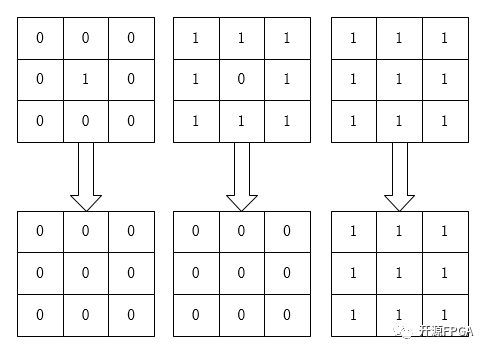
有一個形象的比喻來可以說明該運算,用0表示蛀蟲,1表示大米。蛀蟲腐蝕大米的過程便是腐蝕運算,

腐蝕
如圖所示,對于一個像素矩陣而言,只要有蛀蟲(0)的存在,大米(1)就會被腐蝕掉了,即使只存在一個蛀蟲(0),但是還是會被蛀蟲腐蝕完畢,最后一幅圖上面由于沒有蛀蟲(0)所以大米完好無損。
關于算法的實現,可以用下式子來表示,即3x3像素的運算:
P = P11 & P12 & P13 & P21 & P22 & P23 & P31 & P32 & P33
在FPGA中,為了通過面積去換速度,我們將上式改變如下:
P1 = P11 & P12 & P13
P2 = P21 & P22 & P23
P3 = P31 & P32 & P33
P = P1 & P2 & P3
MATLAB中可以直接寫一個按位或運算。
膨脹
膨脹是將與物體接觸的所有背景點合并到該物體中,使邊界向外部擴張的過程。可以用來填補物體中的空洞。用3X3的結構元素,掃描圖像的每一個像素,用結構元素與其覆蓋的二值圖像做“與”操作,如果都為0,結果圖像的該像素為0,。否則為1。結果使二值圖像擴大一圈。
先腐蝕后膨脹的過程稱為開運算。用來消除小物體、在纖細點處分離物體、平滑較大物體的邊界的同時并不明顯的改變其面積。先膨脹后腐蝕的過程稱為比運算,用來填充物體內細小空間、連接鄰近物體、平滑其邊界的同時并不明顯改變其面積。
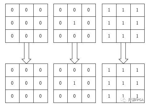
膨脹算法用最簡單的比喻來描述:0表示害蟲,1表示青蛙,青蛙吃了害蟲表示膨脹運算,我們用3*3像素陣列來解釋:

膨脹
如圖所示,圖左只有害蟲(0),所以害蟲都活著,中間那個圖,雖然只有一個害蟲,但是還是會被青蛙全部吃掉,最右邊的那幅圖,都是青蛙,所以青蛙始終是青蛙。
關于算法的實現,可以用下式子來表示,即3x3像素的運算:
P = P11 | P12 | P13 | P21 | P22 | P23 | P31 | P32 | P33
在HDL中,為了通過面積去換速度,我們將上式改變如下:
P1 = P11 | P12 | P13
P2 = P21 | P22 | P23
P3 = P31 | P32 | P33
P = P1 | P2 | P3
MATLAB中可以直接寫一個按位與運算。
開運算閉運算
先腐蝕后膨脹叫開運算,開運算的作用是清除圖像邊緣周圍非邊緣的細小的點。先膨脹后腐蝕為閉運算,閉運算的作用是清除圖像內部的空洞,
如果我們的目標物體外面有很多無關的小區域,就用開運算去除掉;如果物體內部有很多小黑洞,就用閉運算填充掉。
MATLAB邏輯運算函數
bitand(), 對十進制數進行逐位邏輯與運算:先將十進制數轉換成二進制數,然后逐位與運算,其運算結果轉換為十進制。
bitor(), 對十進制數進行逐位邏輯或運算:先將十進制數轉換成二進制數,然后逐位與運算,其運算結果轉換為十進制。
MATLAB代碼實現
1 %RGB_YCbCr  2 clc;  3 clear all;  4 close all;  5   6 RGB_data = imread('lena.jpg');  7   8 R_data =  RGB_data(:,:,1);  9 G_data =  RGB_data(:,:,2);  10 B_data =  RGB_data(:,:,3);  11   12 %imshow(RGB_data);  13   14 [ROW,COL, DIM] = size(RGB_data);
 15   16 Y_data = zeros(ROW,COL);  17 Cb_data = zeros(ROW,COL);  18 Cr_data = zeros(ROW,COL);  19 Gray_data = RGB_data;  20   21 for r = 1:ROW
 22   for c = 1:COL  23     Y_data(r, c) = 0.299*R_data(r, c) + 0.587*G_data(r, c) + 0.114*B_data(r, c);  24     Cb_data(r, c) = -0.172*R_data(r, c) - 0.339*G_data(r, c) + 0.511*B_data(r, c) + 128;  25     Cr_data(r, c) = 0.511*R_data(r, c) - 0.428*G_data(r, c) - 0.083*B_data(r, c) + 128;  26   end  27 end
 28   29 Gray_data(:,:,1)=Y_data;  30 Gray_data(:,:,2)=Y_data;  31 Gray_data(:,:,3)=Y_data;  32   33 figure;  34 imshow(Gray_data);  35   36 %Median Filter  37 imgn = imnoise(Gray_data,'salt & pepper',0.02);
 38   39 figure;  40 imshow(imgn);  41   42 Median_Img = Gray_data;  43 for r = 2:ROW-1  44   for c = 2:COL-1  45     median3x3 =[imgn(r-1,c-1)  imgn(r-1,c) imgn(r-1,c+1)  46           imgn(r,c-1)   imgn(r,c)   imgn(r,c+1)  47           imgn(r+1,c-1)   imgn(r+1,c) imgn(r+1,c+1)];  48     sort1 = sort(median3x3, 2, 'descend'); 49     sort2 = sort([sort1(1), sort1(4), sort1(7)], 'descend');  50     sort3 = sort([sort1(2), sort1(5), sort1(8)], 'descend');  51     sort4 = sort([sort1(3), sort1(6), sort1(9)], 'descend');  52     mid_num = sort([sort2(3), sort3(2), sort4(1)], 'descend');  53     Median_Img(r,c) = mid_num(2);  54   end  55 end  56   57 figure;  58 imshow(Median_Img);  59   60 %Sobel_Edge_Detect  61   62 Median_Img = double(Median_Img);  63 Sobel_Threshold = 150;  64 Sobel_Img = zeros(ROW,COL);  65   66 for r = 2:ROW-1  67   for c = 2:COL-1  68     Sobel_x = Median_Img(r-1,c+1) + 2*Median_Img(r,c+1) + Median_Img(r+1,c+1) - Median_Img(r-1,c-1) - 2*Median_Img(r,c-1) - Median_Img(r+1,c-1);  69     Sobel_y = Median_Img(r-1,c-1) + 2*Median_Img(r-1,c) + Median_Img(r-1,c+1) - Median_Img(r+1,c-1) - 2*Median_Img(r+1,c) - Median_Img(r+1,c+1);  70     Sobel_Num = abs(Sobel_x) + abs(Sobel_y);  71     %Sobel_Num = sqrt(Sobel_x^2 + Sobel_y^2);  72     if(Sobel_Num > Sobel_Threshold)  73       Sobel_Img(r,c)=255;  74     else  75       Sobel_Img(r,c)=0;  76     end  77   end  78 end  79   80 figure;  81 imshow(Sobel_Img);  82   83 %imopen Erosion_Dilation  84 %Erosion  85 % Erosion_img = zeros(ROW,COL);  86 % for r = 2:ROW-1  87   % for c = 2:COL-1  88     % and1 = bitand(Sobel_Img(r-1, c-1), bitand(Sobel_Img(r-1, c), Sobel_Img(r-1, c+1)));  89     % and2 = bitand(Sobel_Img(r, c-1), bitand(Sobel_Img(r, c), Sobel_Img(r, c+1)));  90     % and3 = bitand(Sobel_Img(r+1, c-1), bitand(Sobel_Img(r+1, c), Sobel_Img(r+1, c+1)));  91     % Erosion_img(r, c) = bitand(and1, bitand(and2, and3));  92   % end  93 % end  94   95 % figure;  96 % imshow(Erosion_img);  97   98 % %Dilation  99 % Dilation_img = zeros(ROW,COL);100 % for r = 2:ROW-1101   % for c = 2:COL-1102     % or1 = bitor(Erosion_img(r-1, c-1), bitor(Erosion_img(r-1, c), Erosion_img(r-1, c+1)));103     % or2 = bitor(Erosion_img(r, c-1), bitor(Erosion_img(r, c), Erosion_img(r, c+1)));104     % or3 = bitor(Erosion_img(r+1, c-1), bitor(Erosion_img(r+1, c), Erosion_img(r+1, c+1)));105     % Dilation_img(r, c) = bitor(or1, bitor(or2, or3));106   % end107 % end108 109 % figure;110 % imshow(Dilation_img);111 112 %imclose Erosion_Dilation113 %Dilation114 Dilation_img = zeros(ROW,COL);115 for r = 2:ROW-1116   for c = 2:COL-1117     or1 = bitor(Sobel_Img(r-1, c-1), bitor(Sobel_Img(r-1, c), Sobel_Img(r-1, c+1)));118     or2 = bitor(Sobel_Img(r, c-1), bitor(Sobel_Img(r, c), Sobel_Img(r, c+1)));119     or3 = bitor(Sobel_Img(r+1, c-1), bitor(Sobel_Img(r+1, c), Sobel_Img(r+1, c+1)));120     Dilation_img(r, c) = bitor(or1, bitor(or2, or3));121   end122 end123 124 figure;125 imshow(Dilation_img);126 127 %Erosion128 Erosion_img = zeros(ROW,COL);129 for r = 2:ROW-1130   for c = 2:COL-1131     and1 = bitand(Dilation_img(r-1, c-1), bitand(Dilation_img(r-1, c), Dilation_img(r-1, c+1)));132     and2 = bitand(Dilation_img(r, c-1), bitand(Dilation_img(r, c), Dilation_img(r, c+1)));133     and3 = bitand(Dilation_img(r+1, c-1), bitand(Dilation_img(r+1, c), Dilation_img(r+1, c+1)));134     Erosion_img(r, c) = bitand(and1, bitand(and2, and3));135   end136 end137 138 figure;139 imshow(Erosion_img);
處理后結果對比
為了可以清晰的看到圖像邊緣的變化,我們把黑色作為背景,白色作為邊緣。
Sobel邊緣檢測后的lena
腐蝕后的lena
膨脹后的lena
先腐蝕后膨脹開運算lena
先膨脹后腐蝕閉運算lena
-
matlab
+關注
關注
182文章
2963瀏覽量
230192
原文標題:基于MATLAB的腐蝕膨脹算法實現
文章出處:【微信號:Open_FPGA,微信公眾號:OpenFPGA】歡迎添加關注!文章轉載請注明出處。
發布評論請先 登錄
相關推薦
FFT 算法的一種 FPGA 實現
一種基于FPGA的實時視頻圖像處理算法研究與實現
一種解決函數優化問題的免疫算法
Matlab關于Apriori算法設計


 介紹MATLAB一種算法實現方式


評論