在與電子儀器相關的行業中,與傳統的硅基半導體相比,寬帶隙半導體的創新已被證明是有利可圖且有效的。碳化硅 (SiC)寬帶隙半導體是最先進的半導體之一,具有顯著的相關性。這些半導體在各種參數(如高溫、頻率、電壓和其他幾個參數)上表現相當出色。
通過其成熟的制造工藝,碳化硅 (SiC) 具有無與倫比的電氣特性,使其能夠融入下一代器件制造。SiC-JFET 憑借其快速的開關速度和較低的導通電阻而吸引著市場,使其成為電子行業不斷上升的商業市場中的高需求材料。
隸屬于突尼斯莫納斯提爾大學和法國里昂大學的一組研究人員開發了 JFET 的多維結構,以提高性能并通過對論文中已經提出的模型 進行測試來驗證它,“A Multi -具有橫向通道的 VJFET 的物理模型”[2]。
JFET的布局和特點
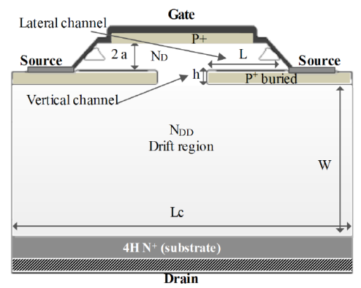
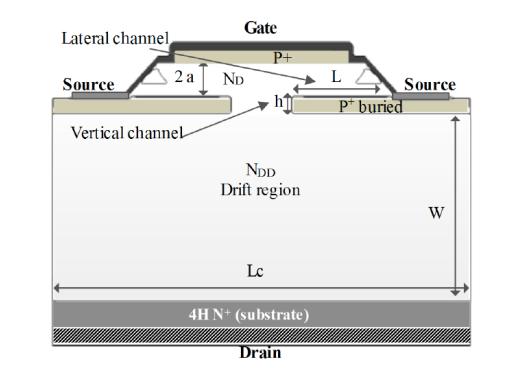
圖 1:SiC JFET 的半電池橫截面?
JFET 是一種單極器件,具有兩個串聯的通道——橫向通道和垂直通道。1200V SiC JFET采用SiCED/INFINION(TO220封裝)制造,裸片尺寸為2.4×2.4mm 2,導通電阻為300mΩ,閾值柵極電壓為-20V,飽和電流為20A。?
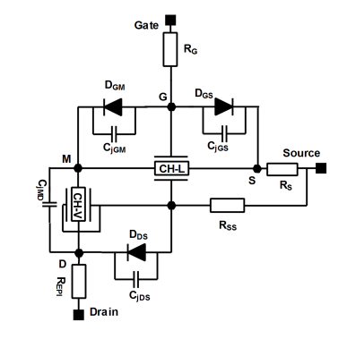
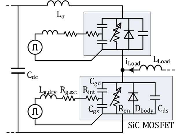
圖 2:JFET 的靜態和動態電路模型
In the static and dynamic circuit model of JFET, we can see three physical capacitances: between gate and source (CjGS), gate and point M (CjGM), and drain and source (CjDS), with an additional capacitor between drain and point M (CjMD). To plot the C-V (Capacitance-Voltage) characteristics, the static and dynamic circuit model undergoes blocking conditions, which means there will be no static current flow in the channel. When the model is under prescribed conditions, the operating frequency is set to 300 kHz, which results in the impedance of the capacitors being greater than all the resistances present in the model circuit.
It is clear in the resultant circuit model shown in figure 3 that the capacitors will only affect the characteristics because the resistances are low in comparison to the capacitors. Taking the total capacitance between each terminal of the JFET, we get CGS, CDS, and CGD. [Note: Two capacitors between gate and drain are in series, hence they are taken as per the formula for resultant (total) capacitance between the two points.
CGS= CJGS
CDS? = CjDS
1/CGD = 1/CjGM + 1/CjMD
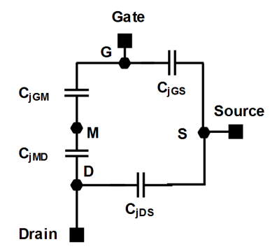
Figure 3: Dynamic circuit model of a SiC JFET in blocking conditions
Numerical simulation?
The researchers decided to use ISE TCAT Software for 2D numerical simulation of the SiC-JFET under predefined parameters, which are available in the research paper.
To start the simulation, a negative gate bias of -20 V is applied to make sure that the JFET is set to the off state. The capacitances can be extracted in the numerical simulations with a small AC signal analysis superimposed on the DC bias voltage when the lateral channel is completely blocked.
下圖顯示了作為測量特性的 C DS (V DS )、C GD (V GD )、C GS (V DS ) 和 C GS (V GS )與從二維數值獲得的特性之間的比較模擬和分析模型。
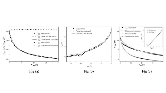
圖 4:C DS (V DS )、C GD (V GD )、C GS (V DS ) 和 C GS (V GS ) 的模擬
數值模擬分析
在數值模擬之后,分析了電容 CGD、CGS 和 CDS 的結果和測量值,電容值與相關空間電荷 (SCR) 寬度有關。以下標準將應用于 SCR 邊界的計算。

等式 1:計算 SCR 的邊界
由上式可知,Г(x) 是凈摻雜濃度,p(x,t) 是凈空穴濃度,n(x,t) 是電子濃度,其中 x 和 t 分別是空間和時間變量。??
平面結柵源 C GS和 C DS電容與 V DS的測量、數值模擬和分析模型分別呈現在模擬圖中。根據 C DS模型的方程,已經觀察到 C GS(以圓圈和頂部箭頭表示,約 400pF 電容)隨 V DS微弱增加,但 C GS取決于 V GS并且類似于柵源平面電容。研究人員注意到,在這種情況下,實驗和模擬結果是一致的,這在 CDS 和 CGS 電容的第三種情況下是不正確的,其中 CGD 電容不適合平面結電容。為了解決這種差異,該團隊基于 TCAD 數值分析,提出了 CGD 電容的解析模型。
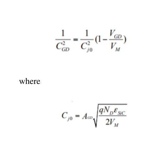
公式 2:C GD電容的分析模型
使用分析模型,可以得出結論,CGD 測量的電容與計算的電容之間存在相關性。
SiC JFET 動態模型驗證
驗證所提出的方法對于任何實驗都非常重要。為此,該團隊進行了測試,以評估切換情況下動態性能的有效性。負載電阻R、負載電感L和柵極電阻RG都是電感開關模擬電路的一部分。
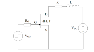
圖 5:用于感應開關仿真的電路
查看電感電阻開關關斷的仿真(藍色波形)和實驗(綠色波形)結果的比較,我們可以看到兩者非常吻合。對于感阻開關關斷,我們看到兩個結果彼此非常吻合。兩個波形重合的點是理想點。但是,在實際場景中,誤差會有所不同。目的是減少誤差以獲得優化的結果。?
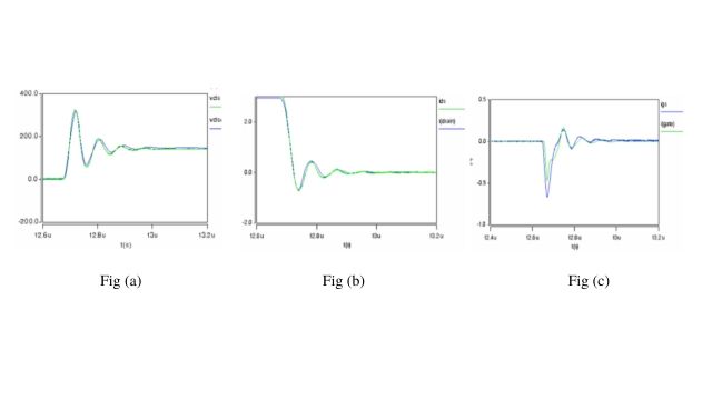
圖6:感阻開關關斷波形
結論與分析
該研究文章基于中開展的工作,旨在改進和驗證 JFET 的多維結構。在阻斷條件下(靜態電流 = 0A),從 JFET 的靜態和動態電路模型開始,在 JFET 的每個端子之間產生串聯和并聯電容器。CV 特性的數值模擬顯示了不同的結果,其中一些結果與其他結果不遵循相同的模式。在這篇研究文章中,該團隊開發了一個具有橫向通道的垂直 SiC JFET 的動態模型,該模型考慮了終端電容中的多功能效應。后來,動態模型在VHDL-AMS軟件中進行,?
審核編輯:劉清
?
 電子發燒友App




















評論