Abstract: Maxim manufactures several delay lines. This application note compares each programmable delay line and non-programmable delay line to help customers choose the appropriate device for their application. Since many of the features of these devices cannot easily be categorized into fields in the on-line parametric database, the intent of this application note is to show a side-by-side comparison of members of the delay line family and to eliminate the hassles of sifting through numerous data sheets when trying to select a device.
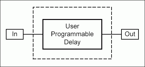
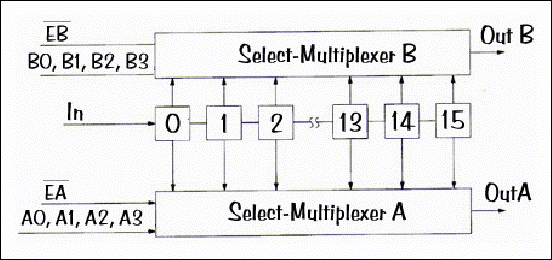
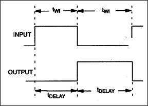
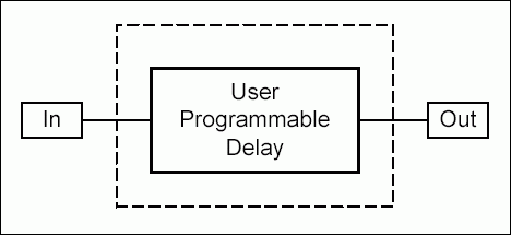
Figure 1. Programmable delay line functional diagram.
Table 1. Programmable delay lines comparison
Note: Device specifications have been provided here for device comparison. In the case of discrepancy between this application note and the data sheet, the data sheet supersedes this application note.
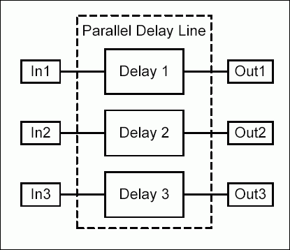
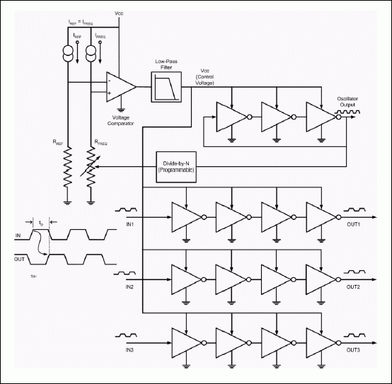
Figure 2. Non-programmable 3-in-1 parallel delay line functional diagram.
Table 2. Non-programmable parallel delay lines comparison
Note: Device specifications have been provided here for device comparison. In the case of discrepancy between this application note and the data sheet, the data sheet supersedes this application note.

Figure 3. Non-programmable 5-tap delay line functional diagram.
Table 3. Non-programmable tapped delay lines comparison
Note: Device specifications have been provided here for device comparison. In the case of discrepancy between this application note and the data sheet, the data sheet supersedes this application note.
Application Notes for delay lines can be found at http://www.maxim-ic.com/appnotes10.cfm/ac_pk/10.
Ordering Information
Programmable Delay Lines Comparison
Maxim's programmable delay lines operate from a 5.0V supply and are available in SO or DIP packages. Programmable delay lines offer the customer the ability to program delays after the device has been installed in the application. Each device is described below and key features are compared in Table 1. A functional diagram of a programmable delay line is shown in Figure 1.
Figure 1. Programmable delay line functional diagram.
DS1020
The DS1020 is an 8-bit delay line. The DS1020 is available in 5 versions (dash numbers) with different step sizes (0.15ns, 0.25ns, 0.5ns, 1ns, and 2ns). Delays are available from 10ns to 520ns and can be programmed using the 3-wire serial interface or the 8-bit parallel interface.DS1021
The DS1021 is identical to the DS1020 except it is available in only two step sizes (0.25ns and 0.5ns) and it has a minimum VCC power-up time. Delays are available from 10ns to 137.5ns and can be programmed using the 3-wire serial interface or the 8-bit parallel interface.DS1023
The DS1023 is similar to the DS1020/1021 with a few added features. This device has the ability to delay signals by up to a full period or more and the signal can also be inverted. The DS1023 can also output a pulse-width modulated signal. The on-chip reference delay creates a step zero delay of 0ns. Delays are available from 0ns to 1275ns with 5 different step sizes (0.25ns, 0.5ns, 1ns, 2ns, and 5ns) and can be programmed using the 3-wire serial interface or the 8-bit parallel interface.DS1040
The DS1040 is an adjustable one-shot pulse generator. Pulse widths are available from 5ns to 500ns and steps can be programmed from 2.5ns to 100ns, depending on version, using the parallel interface.DS1045
The DS1045 is a 4-bit dual delay line. This device has two independently programmable outputs. Delays are available from 9ns to 84ns in 3ns, 4ns, or 5ns steps (depending on version) and can be programmed using the parallel interface.Table 1. Programmable delay lines comparison
| ? | DS1020 | DS1021 | DS1023 | DS1040 | DS1045 |
| VCC | 5V | 5V | 5V | 5V | 5V |
| Package | 16 pin DIP, 16 pin SO | 16 pin SO | 16 pin DIP, 16 pin SO | 8 pin DIP, 8 pin SO | 16 pin DIP, 16 pin SO |
| Step Sizes Available (ns) | 0.15, 0.25, 0.5, 1, 2 | 0.25, 0.5 | 0.25, 0.5, 1, 2, 5 | 2.5, 15, 20, 30, 40, 50, 100 | 3, 4, 5 |
| Number of Program Steps | 256 | 256 | 256 | 5 | 16 |
| Min/Max Delay of Pulse Width (ns) | 10/520 | 10/138 | 0/1275 | 5/500 | 9/84 |
| Enable? | Yes | Yes | Yes | No | Yes |
| Reference/PWM Output? | No | No | Yes (REF/PWM pin) | No | No |
| Active Supply Current | 30mA | 30mA | 60mA | 75mA | 35mA |
| Number of Outputs | 1 | 1 | 1 | 2 (OUT, OUT pins) | 2 |
| Programming Interface | 3-wire or 8-bit parallel | 3-wire or 8-bit parallel | 3-wire or 8-bit parallel | 3-bit parallel | 4-bit parallel |
Non-Programmable Delay Lines Comparison
Tables 2 and 3 list some of the device specifications for each non-programmable delay line. There are parallel and tapped non-programmable delay lines.Parallel Delay Lines
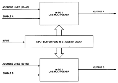
The devices listed below are parallel delay lines. Parallel delay lines have multiple, independent delay cells. See Figure 2 for a functional diagram of a parallel delay line.
Figure 2. Non-programmable 3-in-1 parallel delay line functional diagram.
DS1013/DS1135/DS1135L
The DS1013, DS1135, and DS1135L are 3-in-1 silicon delay lines. The DS1135 is a 5.0V high-speed version and the recommended replacement for the DS1013 and DS1035. The DS1135L is the 3.3V version of the DS1135 and the recommended replacement for the DS1033. All these devices have leading and trailing edge accuracy. The DS1135/DS1135L have a better nominal delay tolerance than the DS1013. The nominal delay tolerance for the DS1013 is ±2.0ns and the nominal delay tolerance for the DS1135/DS1135L is ±1.0ns. The DS1013 has 17 versions (dash numbers) available with delays from 10ns to 200ns. The DS1135 has 8 versions with delays from 6ns to 30ns. The DS1135L has 6 versions with delays from 10ns to 30ns.DS1033/DS1035
The DS1033 is a 3.3V device and the DS1035 is a 5.0V device. Both devices have 3 independent delays with leading- and trailing-edge accuracy. The nominal delay tolerance is ±1.5ns. The DS1033 has 7 versions with delays from 8ns to 30ns. The DS1035 has 8 versions with delays ranging from 6ns to 30ns. The DS1135 is the recommended replacement for the DS1035 and the DS1135L is the recommended replacement for the DS1033.DS1044
The DS1044 has the same tolerance as the DS1035 but it has 4 delays instead of 3 delays. Also, the available delays are slightly different. The DS1044 has 10 versions available with delays from 5ns to 25ns. The nominal delay tolerance is ±1.5ns.DS1007
The DS1007 has 7 delays. The first 4 delays (1 to 4) can be set between 3ns and 10ns and have leading edge accuracy only. The last 3 delays (5 to 7) can be set between 9ns and 40ns and have leading and trailing edge accuracy. The nominal delay tolerance is ±2.0ns.Table 2. Non-programmable parallel delay lines comparison
| ? | DS1013 | DS1033 | DS1035 | DS1135 | DS1135L | DS1044 | DS1007 |
| VCC | 5V | 3.3V | 5V | 5V | 3.3V | 5V | 5V |
| Package | 14 pin DIP, 16 pin SO, 8 pin DIP | 8 pin DIP, 8 pin SO | 8 pin DIP, 8 pin SO | 8 pin DIP, 8 pin SO, 8 pin μSOP | 8 pin SO, 8 pin μSOP | 14 pin DIP, 14 pin SO | 16 pin DIP, 16 pin SO |
| Number of Independent Delays | 3 | 3 | 3 | 3 | 3 | 4 | 7 |
| Total Delays Available (ns) | 10 to 200 | 8 to 30 | 6 to 30 | 6 to 30 | 10 to 30 | 5 to 25 | 3 to 10, 9 to 40 |
| Nominal Tolerance | ±2.0ns | ±1.5ns | ±1.5ns | ±1.0ns | ±1.0ns | ±1.5ns | ±2.0ns |
Tapped Delay Lines
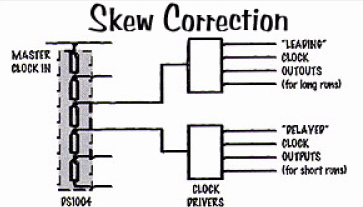
The devices listed below are tapped delay lines with leading and trailing edge accuracy. Tapped delay lines have multiple delay cells in series. A tapped delay is useful when an application requires a delay line with one input and multiple delayed outputs such as for multiphased clocks. See Figure 3 for a tapped delay line functional diagram.
Figure 3. Non-programmable 5-tap delay line functional diagram.
DS1000
The DS1000 is obsolete but has been replaced with the pin-to-pin compatible DS1100. See the DS1100/DS1110L section below.DS1004
The DS1004 is a 5-tap delay line. Delays range from 5ns to 25ns. The step size varies from 2ns to 5ns depending on the version of the device. The input-to-tap nominal delay tolerance is ±1.5ns. The DS1004 also has a tap-to-tap nominal tolerance of ±0.75ns.DS1005
The DS1005 is also a 5-tap delay line but with larger delays and step sizes than the DS1004. Delays range from 12ns to 250ns. The step size varies from 12ns to 50ns depending on the version of the device. The input-to-tap nominal delay tolerance is ±2ns.DS1100/DS1100L
The DS1100 and DS1100L are 5-tap delay lines. The DS1100 and DS1100L are improved, drop-in replacements for the DS1000 in 5V and 3.3V versions, respectively. Delays range from 4ns to 500ns. The step size varies from 4ns to 100ns depending on the version of the device. The input-to-tap nominal delay tolerance is ±2ns.DS1010
The DS1010 is a 10-tap delay line. Delays range from 5ns to 500ns. The step size varies from 5ns to 50ns depending on the version of the device. The input-to-tap nominal delay tolerance is ±2ns.DS1110/DS1110L
The DS1110 and DS1110L are 10-tap delay lines. The DS1110 and DS1110L are improved, drop-in replacements for the DS1010 in 5V and 3.3V versions, respectively. Delays range from 5ns to 500ns for the DS1110 and the step size varies from 5ns to 50ns depending on the version of the device. Delays range from 10ns to 500ns for the DS1110L and the step size varies from 10ns to 50ns depending on the version of the device. The input-to-tap nominal delay tolerance is ±2ns for the DS1110/DS1110L.Table 3. Non-programmable tapped delay lines comparison
| ? | DS1004 | DS1005 | DS1100 | DS1100L | DS1010 | DS1110 | DS1110L |
| VCC | 5V | 5V | 5V | 3.3V | 5V | 5V | 3.3V |
| Package | 8 pin DIP, 8 pin SO | 14 pin DIP, 16 pin SO, 8 pin DIP | 8 pin DIP, 8 pin SO, 8 pin μSOP | 8 pin DIP, 8 pin SO, 8 pin μSOP | 14 pin DIP, 16 pin SO | 14 pin DIP, 16 pin SO, 14 pin TSSOP | 14 pin TSSOP |
| Number of Taps | 5 | 5 | 5 | 5 | 10 | 10 | 10 |
| Delat to First Tap (ns) | 5 | 12 to 50 | 4 to 60 | 4 to 60 | 5 to 100 | 5 to 50 | 5 to 50 |
| Tap Increment (Step size) (ns) | 2, 3, 4, or 5 | 12 to 50 | 4 to 100 | 4 to 100 | 5 to 100 | 5 to 50 | 5 to 50 |
| Total Delays Available (ns) | 5 to 25 | 12 to 250 | 4 to 500 | 4 to 500 | 5 to 500 | 5 to 500 | 5 to 500 |
| Nominal Tolerance | ±1.5ns | ±2ns | ±5ns | ±5ns | ±5ns | ±5ns | ±5ns |
Conclusion
This application note compares Maxim's delay lines to assist customers in choosing the appropriate device for their application. This comparison will prevent customers from sifting through multiple data sheets and the on-line parameter database. For further information contact Applications Support at MixedSignal.Apps@dalsemi.com.Application Notes for delay lines can be found at http://www.maxim-ic.com/appnotes10.cfm/ac_pk/10.
Ordering Information
 電子發燒友App









評論