Introduction
The Ultra-High-Speed Microcontroller family uses a single-clock cycle core that is up to 12 times faster than a traditional 8051 at identical clock frequencies. Members of the Ultra-High-Speed Microcontroller family include varying amounts of internal flash memory and MOVX SRAM to allow for simple system design. These microcontrollers have several features including two full-duplex serial ports, three timer counters, four bidirectional I/O ports, and six external interrupt sources. While they do not have a hardware serial peripheral interface (SPI) port, one can easily be emulated by software.This application note uses a full-featured software SPI master for ultra-high-speed microcontrollers and a simple application that makes use of it to control a Crystalfontz LCD (www.crystalfontz.com).
Application Overview
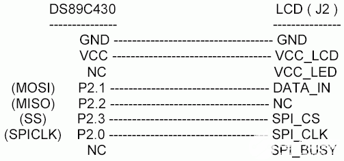
The application accepts ASCII data at 57,600 baud (when using a 33MHz crystal) on serial port 0 from a standard serial terminal program. The data is echoed back to the terminal and stored in data memory until a carriage return is detected; then the accumulated text is displayed on the LCD. The LCD used in this application is a Crystalfontz SKD204-634 V2.0 serial LCD that has a low-speed SPI interface. It is connected to a DS89C430 as shown in Figure 1. After a reset, the banner "DS89C430 Software SPI Application Note" is printed to the terminal. When the application is listening for input data it prints a "=>" prompt.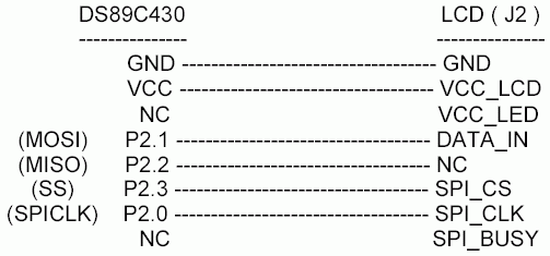
Figure 1. Connection diagram.
Software SPI Library
The software SPI library used by this application is a highly configurable SPI master with the following features:| - | Four SPI Clock Modes |
| - | 8- and 16-Bit Word Transfers |
| - | SPI Clock Stretching |
| - | Optional Atomic Transfers |
The four SPI clock (SPI_CLK) modes supported by this library are defined by CKPHA and CKPOL. The CKPOL bit defines the idle state of the SPI clock, CKPOL = 0 forces SPI_CLK to idle low, while CKPOL = 1 forces SPI_CLK to idle high. CKPHA changes the edge used to signal transfer of data. When CKPHA = 0, the first edge of SPI_CLK specifies when the slave and master should sample their input. With CKPHA = 1, the second edge of SPI_CLK specifies when to sample. When CKPHA = 1, the master and slave should present their data on their output during the first SPI_CLK edge. This allows the data sufficient hold time. When CKPHA = 0, data should become valid when the Slave Select (SS) line goes active. Note that most devices require the SS line to be used when CKPHA = 0 to allow proper timing, while SS may be optional when CKPHA = 1. Figure 2 illustrates this behavior.
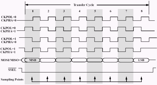
Figure 2. SPI timing diagram.
Data is sent to the SPI library as a byte array in data memory. When in 8-bit word mode, these bytes are transferred one at a time. In 16-bit word mode, two bytes are transferred, but this operation only consumes one transfer of the number requested. Note that in this document, "word" may be 8 or 16 bits in length depending on the selected mode.
To interface to slower SPI slaves, a SPI_CLK stretch can be used to increases the SPI_CLK period by 1μs per stretch.
The SS signal is optional as it may not be required for all SPI setups. Most SPI devices expect the active state for SS to be low, but others require high as the active state. Some SPI devices expect the SS signal to go inactive after each word transfer to synchronize.
To facilitate atomic transfers, interrupts may be disabled while transmitting.
Software SPI Library Interface
Interfacing to the SPI library is done as follows. The data to be transferred must be located in a contiguous section of data memory as an array. The library requires that data pointer zero (dptr0) point to the beginning of the data to be transferred. The number of words to transfer should be placed in R3, R2, R1, and R0, R3 being the MSB. The desired stretch value should be placed in R4. Options for the SPI library should be placed into R5 with its bit values defined as:| R5.0 - CKPOL | Set to 1 - SPI_CLK idles high |
| R5.1 - CKPHA | Set to 1 - Transfer on second SPI_CLK edge |
| R5.2 - wordMode | Set to 1 - Use 16-bit word transfers |
| R5.3 - noSkew | Set to 1 - Turn off interrupts during transfer |
| R5.4 - useSS | Set to 1 - Use the SS line during transfers |
| R5.5 - synchSS | Set to 1 - Take SS inactive after every word |
| R5.6 - invertSS | Set to 1 - SS line is active high |
| R5.7 - undefined |
Once all registers are setup, start the transfer by calling the xmitSPI function. After the transfer has completed, the data read during each word transfer will be located in the corresponding word location in the data array passed for the transfer. Note that dptr0 will point to the beginning of the transfer array after the call to xmitSPI, but the data pointed to will be changed.
Code Listing: Software SPI and Crystalfontz LCD
This application was built using Keil μVision2?, but with a few modifications, any 8051 assembler could be used. The application and SPI library source and binaries can be found on our ftp site: http://files.dalsemi.com/microcontroller/app_note_software/. To report any library bugs or for support, please email micro.software@dalsemi.com.SPI is a trademark of Motorola, Inc.
 電子發(fā)燒友App







評(píng)論