Abstract: RS-232 features are explained in a way that makes it easy to select an appropriate RS-232 communication IC to meet any system need. Special attention is given to, signal swings, slew rates, enhanced ESD protection as well as data rates up to 1Mbaud. The concept of RS-232 compatible vs. RS-232 compliant is introduced where system needs may suggest high data rates or low supply voltages. Products are identified to meet low-power system needs with automatic shutdown to low-power mode and auto wakeup, low supply voltages, high ESD protection, programmable logic thresholds, and high data and slew rates.
As of January 2001, Maxim makes more than 124 RS-232 parts. To help you choose the most appropriate part for an application, this article explains the different features available.
What does all of this mean? For starters, these parts are not strictly RS-232-compliant. In other words, if a MegaBaud-capable part is plugged into an ordinary RS-232-compliant port, proper operation cannot be guaranteed even at data rates as low as 20kbps. In reality, however, the lower data rates will probably work fine. But running at 1Mbps is a different story. In order to guarantee 1Mbps data rates, both ends of the cable must have parts that are capable of MegaBaud operation.
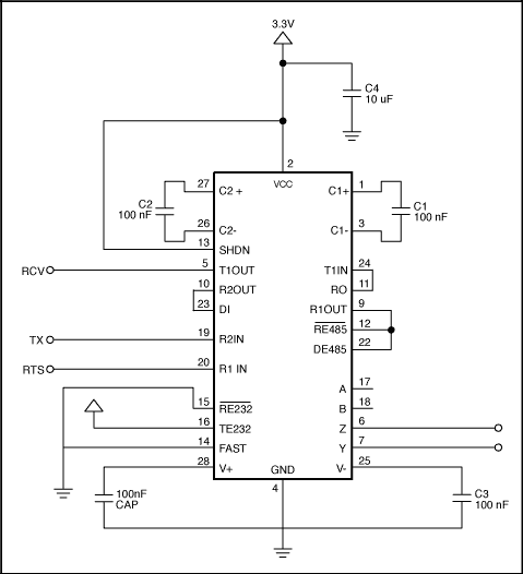
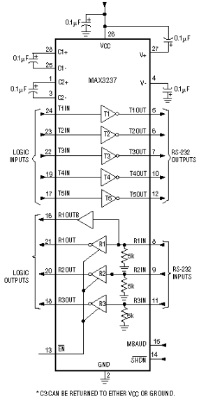
An interesting feature available on some MegaBaud-capable parts is a pin labeled MBAUD. See Figure 1. This pin configures the part to operate at either an RS-232-compliant slew rate of less than 30V/μs or at a higher slew rate to allow MegaBaud operation. This means the part has the best of both worlds. When connected to an ordinary RS-232 port, the part can function in a truly RS-232-compliant mode; however, when it is connected to another MegaBaud-capable part, it can switch gears and transmit at 1Mbps or greater.

Figure 1. The MAX3237 has a pin labeled MBAUD that allows it to switch between RS-232-compliant 250kbps data rates and 1Mbps data rates.
Some applications require the +/-15kV ESD protection on both the RS-232 pins and the CMOS pins. A typical example is with cell phones. In order to save cost and size, the cell phone does not include the RS-232 transceiver in the phone itself. Instead, it brings CMOS-level signals out the connector at the bottom of the phone. If the owner of the phone wants to connect to the RS-232 port of a laptop, for instance, he or she must buy a special cable sometimes referred to as a "data lump." This data lump has an RS-232 transceiver mounted within the cable itself. See Figure 2. This increases the cost of the cable; but in the long run, because fewer cables are sold than phones, money is saved. That's the good news. The bad news is that now both sides of the RS-232 transmitters and receivers are brought out to connectors, exposing them to increased ESD risk. In such cases, it can be desirable to have extended ESD protection on both the CMOS and RS-232 sides of the transmitters and receivers. Maxim has a few parts that do just that. Examples include the MAX3238E, MAX3237E, MAX3248E, MAX3380E, and MAX3381E.
It is important to note how our parts respond during ESD strikes. Not only will the parts not be damaged by ESD strikes less than their rated value, but they also will continue to work normally without having to recycle power. In addition, they are protected against ESD strikes while powered up, powered down, and in shutdown.
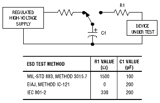
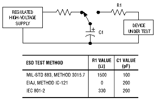
Table 1. The Level of ESD Protection on Maxim's Standard RS-232 Parts vs. the +/-15kV Protected Parts
(ESD levels were measured using the Human Body and IEC1000-4-2 method.)

Figure 2. The MAX3238E and the MAX3248E shown in a typical "data-lump" application; because both the RS-232 signals and the CMOS signals are brought to connecters, they have +/-15kV ESD protection on these pins.
In the real world, a lot of RS-232 devices are used for only small fractions of time. Most laptop users, for example, typically don't use their RS-232 ports at all. If nothing is connected to the RS-232 port, it makes sense to put the RS-232 part into a low-power mode. Autoshutdown is a feature designed to do exactly that. What makes it especially powerful is that it doesn't require any processor involvement. This means power can be saved without having to make special provisions in software.
Autoshutdown works by monitoring the RS-232 side of the receivers. When connected to another RS-232 device, the receivers will see valid RS-232 signals that are either below -3V or above +3V. On the other hand, if nothing is connected, the receivers will typically be at ground. If the Autoshutdown feature detects that all the receivers are between -.3V and +.3V for greater than 30μS, it assumes that a valid transmitter is not connected and will automatically put itself into a low-power mode. See Figures 3 and 5. The part will automatically take itself out of the low-power mode if any one of the receivers' inputs exceeds +2.7V or goes below -2.7V. See Figures 4 and 5.

Figure 3. Autoshutdown is entered if all receivers' inputs are between +/-.3V for at least 30μS.

Figure 4. Autoshutdown is exited if any receiver exceeds +/-2.7V.

Figure 5. The trip levels for entering and exiting Autoshutdown.
In low-power mode, the transmitters and the charge-pump converters used by the transmitters are turned off. However, because the receivers themselves take very little current to operate, they are kept active. The overall effect is a reduction of quiescent current from .3mA to 1μA typical (1mA to 10μA max) for the MAX3221. It is important to keep in mind that it takes on the order of 100μS for the transmitters to become fully active once valid RS-232 levels are detected on the receivers.
Examples of parts that have the Autoshutdown feature:

Figure 6. Autoshutdown parts, such as the MAX3221, have pins labeled ForceOn, ForceOff*, and Invalid* that increase their functionality.
Table 2. The State Table for Typical Autoshutdown Parts
Examples of parts that have the Autoshutdown feature:
Autoshutdown Plus shares the same features as Autoshutdown, such as ForceOn, ForceOff*, and Invalid*. There are, however, a couple of interesting things to note about Autoshutdown Plus. The first is that Autoshutdown Plus monitors both the receivers and the transmitters for activity. The second is that Autoshutdown Plus can be made to behave like Autoshutdown if the Invalid* line is tied to both ForceOn and ForceOff*. See Figure 7.

Figure 7. By connecting the ForceOn and ForceOff* inputs to the Invalid* outputs, an Autoshutdown Plus part can be made to behave like an Autoshutdown part.
Examples of parts that have the Autoshutdown Plus feature:
As with the MAX3223, most parts that have receivers active in shutdown also have an EN* pin. Pulling this pin low puts the outputs of the receivers into a high-Z state. To understand the reason for this pin, see Figure 8. In many cases the RS-232 part is connected to a UART. When the RS-232 part is placed in shutdown, it isn't uncommon for the system to remove power from the UART to also save power. This means that the Vcc pin of the UART will be at ground. If the output of the RS-232 receiver is high, it will forward-bias the protection diode built into the UART. This causes excessive current to flow, defeating the whole purpose of putting the unit into shutdown. The EN* pins allow the receiver outputs to be put into a high-Z state, preventing this problem.

Figure 8. Some Maxim RS-232 devices have EN* pins that allow the receivers to go into high-Z mode, so that the receivers won't forward-bias parts whose power supplies have been shut down to save power.
Several of Maxim's parts, whose receivers are not active in shutdown, provide an additional receiver tied in parallel to one of the usual receivers. See Figure 9. This allows the UART to be powered down, while also permitting the RS-232 port to be monitored for activity by other circuitry.
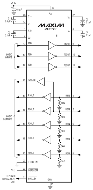
Figure 9. The MAX3243 has an extra receiver, R2OUTB, which remains active even while the other receivers are put into a high-Z output state.

Figure 10. The MAX3386E includes a Vl pin that allows the logic thresholds to be programmed for mixed-voltage systems.
This distinction is important, because an RS-232-compatible, but not RS-232-compliant, part can be powered from +/-5V supplies without the need for charge pumps. Without the charge pumps, the part becomes smaller and cheaper. This is exactly the case with the MAX3314E. The MAX3314E works off +/-5V +/-5% supplies, guaranteeing +/-3.7V swings when fully loaded. This swing is enough to properly drive all RS-232-compliant receivers, but reduces the noise margin from 2V to .7V. Designers who are considering making this compromise must carefully weigh the advantages of smaller size and lower cost against this reduced-noise margin and the fact that their system will not be truly RS-232-compliant.
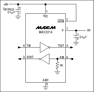
Figure 11. The MAX3314E runs off of +/-5V supplies, but does not have charge-pump doublers and inverters. This makes the part smaller, cheaper, and RS-232-compatible, but not RS-232-compliant.
Another interesting Maxim part is the MAX3316. This part approaches the situation in another direction. It is designed to run in systems that are powered from 2.25V to 3.0V. Previously, the only Maxim solutions available for this supply range were the inductor-based parts, such as the MAX3218. Inductor-based solutions work great and are RS-232-compliant, but tend to be a bit bulkier and slightly more expensive than their capacitor counterparts. The MAX3316 provides a capacitor-based solution, at the expense of being RS-232-compatible and not RS-232-compliant. It works exactly as the 3.0V to 5V parts, except its charge pumps are designed to work down to 2.25V. With these low supply voltages, the part is unable to guarantee RS-232-compliant output swings, but can ensure RS-232-compatible outputs of +/-3.7V.
___________________________
*This designates an active low signal; the line above the text in the figures means the same thing.
As of January 2001, Maxim makes more than 124 RS-232 parts. To help you choose the most appropriate part for an application, this article explains the different features available.
Power Supplies
A separate article, Selecting and Using RS-232 Interface Parts For Your Power Supply Voltages, describes the RS-232 parts available for different power supply voltages.Data Rate
Just about all Maxim RS-232 parts will transmit and receive data at up to 120kbps, with most parts being capable of rates as high as 250kbps. All of this is done while conforming to the 30V/μs maximum slew rate designated in the RS-232 specification (officially called TIA/EIA-232-F). Higher data rates are available, but require special mention.MegaBaud
MegaBaud is the term Maxim uses for RS-232-logic-level-compatible data rates that are 1Mbps or higher. A keen observer would notice that the word "compatible" is used here as opposed to "compliant." This is a subtle and important point that needs further explanation. Buried deep within the RS-232 specification is a limit that states that the slew rate of a transmitter must be less than 30V/μs. This limit was specified in the interest of making RS-232 a simple physical interface. Without this limit, much closer attention must be paid to things such as radiated emissions and some transmission-line effects. Although this slew-rate limit makes the physical interface simpler, it also effectively limits the maximum data rate that can reasonably be used. Maxim makes a series of parts that are capable of MegaBaud operation and meet the RS-232 specification except for this slew-rate limit. To ensure that the physical interface remains simple, these series of parts are still slew-rate-limited but have a higher limit than allowed in the RS-232 specification (150V/μs in the case of the MAX3237E).What does all of this mean? For starters, these parts are not strictly RS-232-compliant. In other words, if a MegaBaud-capable part is plugged into an ordinary RS-232-compliant port, proper operation cannot be guaranteed even at data rates as low as 20kbps. In reality, however, the lower data rates will probably work fine. But running at 1Mbps is a different story. In order to guarantee 1Mbps data rates, both ends of the cable must have parts that are capable of MegaBaud operation.
An interesting feature available on some MegaBaud-capable parts is a pin labeled MBAUD. See Figure 1. This pin configures the part to operate at either an RS-232-compliant slew rate of less than 30V/μs or at a higher slew rate to allow MegaBaud operation. This means the part has the best of both worlds. When connected to an ordinary RS-232 port, the part can function in a truly RS-232-compliant mode; however, when it is connected to another MegaBaud-capable part, it can switch gears and transmit at 1Mbps or greater.

Figure 1. The MAX3237 has a pin labeled MBAUD that allows it to switch between RS-232-compliant 250kbps data rates and 1Mbps data rates.
Extended ESD
All Maxim devices incorporate ESD-protected structures on all pins to protect against electrostatic discharges encountered during handling and assembly. Maxim's standard RS-232 parts offer > = 2kV ESD protection. Maxim's +/-15kV protected parts improve upon this by offering (as one might suspect) +/15kV protection on their RS-232 transmitter-output and receiver-input pins. Everything in life has a price, and the added ESD protection comes at a small cost. The +/-15kV protected parts are usually the same pinout and functionality as the standard parts, allowing these parts to be easily substituted without modification to the board layout. The MAX202 and the MAX202E are examples of two such parts. The MAX202 has the standard level of protection, whereas the MAX202E has the +/-15kV protection.Some applications require the +/-15kV ESD protection on both the RS-232 pins and the CMOS pins. A typical example is with cell phones. In order to save cost and size, the cell phone does not include the RS-232 transceiver in the phone itself. Instead, it brings CMOS-level signals out the connector at the bottom of the phone. If the owner of the phone wants to connect to the RS-232 port of a laptop, for instance, he or she must buy a special cable sometimes referred to as a "data lump." This data lump has an RS-232 transceiver mounted within the cable itself. See Figure 2. This increases the cost of the cable; but in the long run, because fewer cables are sold than phones, money is saved. That's the good news. The bad news is that now both sides of the RS-232 transmitters and receivers are brought out to connectors, exposing them to increased ESD risk. In such cases, it can be desirable to have extended ESD protection on both the CMOS and RS-232 sides of the transmitters and receivers. Maxim has a few parts that do just that. Examples include the MAX3238E, MAX3237E, MAX3248E, MAX3380E, and MAX3381E.
It is important to note how our parts respond during ESD strikes. Not only will the parts not be damaged by ESD strikes less than their rated value, but they also will continue to work normally without having to recycle power. In addition, they are protected against ESD strikes while powered up, powered down, and in shutdown.
Table 1. The Level of ESD Protection on Maxim's Standard RS-232 Parts vs. the +/-15kV Protected Parts
(ESD levels were measured using the Human Body and IEC1000-4-2 method.)
| ? |
|
|
|
| RS-232 Driver-Output and Receiver-Input Pins |
|
|
|
| CMOS Driver-Input and Receiver-Output Pins |
|
|
|

Figure 2. The MAX3238E and the MAX3248E shown in a typical "data-lump" application; because both the RS-232 signals and the CMOS signals are brought to connecters, they have +/-15kV ESD protection on these pins.
Autoshutdown
Autoshutdown is a feature intended to save power. It works by placing the RS-232 device into a low-power shutdown mode whenever it detects the RS-232 interface isn't being used.In the real world, a lot of RS-232 devices are used for only small fractions of time. Most laptop users, for example, typically don't use their RS-232 ports at all. If nothing is connected to the RS-232 port, it makes sense to put the RS-232 part into a low-power mode. Autoshutdown is a feature designed to do exactly that. What makes it especially powerful is that it doesn't require any processor involvement. This means power can be saved without having to make special provisions in software.
Autoshutdown works by monitoring the RS-232 side of the receivers. When connected to another RS-232 device, the receivers will see valid RS-232 signals that are either below -3V or above +3V. On the other hand, if nothing is connected, the receivers will typically be at ground. If the Autoshutdown feature detects that all the receivers are between -.3V and +.3V for greater than 30μS, it assumes that a valid transmitter is not connected and will automatically put itself into a low-power mode. See Figures 3 and 5. The part will automatically take itself out of the low-power mode if any one of the receivers' inputs exceeds +2.7V or goes below -2.7V. See Figures 4 and 5.

Figure 3. Autoshutdown is entered if all receivers' inputs are between +/-.3V for at least 30μS.

Figure 4. Autoshutdown is exited if any receiver exceeds +/-2.7V.

Figure 5. The trip levels for entering and exiting Autoshutdown.
In low-power mode, the transmitters and the charge-pump converters used by the transmitters are turned off. However, because the receivers themselves take very little current to operate, they are kept active. The overall effect is a reduction of quiescent current from .3mA to 1μA typical (1mA to 10μA max) for the MAX3221. It is important to keep in mind that it takes on the order of 100μS for the transmitters to become fully active once valid RS-232 levels are detected on the receivers.
Examples of parts that have the Autoshutdown feature:
- MAX221/E
- MAX3212
- MAX3218
- MAX3221
- MAX3223
- MAX3243
ForceOn/ForceOff*
All parts with the Autoshutdown feature have two pins labeled ForceOn and ForceOff*. These pins allow the user to manually override the Autoshutdown feature with software control. Pulling ForceOff* low will force the part into shutdown. This occurs independently of the current state of the part. Pulling ForceOn high forces the part into normal operation, again independently of the part's current state. If both ForceOff* is pulled low and ForceOn is pulled high, the part will be forced into shutdown. See Table 2.
Figure 6. Autoshutdown parts, such as the MAX3221, have pins labeled ForceOn, ForceOff*, and Invalid* that increase their functionality.
Invalid*
Anther handy feature of Autoshutdown is the Invalid* pin. This pin goes high whenever a valid RS-232 level is present on any one of the receivers. This is an indication that another RS-232 device is connected. Processors can monitor this pin to let software know when the port can be used. This can be helpful, for example, in systems that use an RS-232 device as a debug port. A debug port will usually have nothing connected to it in normal operation. However, whenever a problem occurs, a technician will connect to the port and download debug information. By monitoring the Invalid* pin, the processor can tell when a technician has connected and can execute its debug routines.Table 2. The State Table for Typical Autoshutdown Parts
|
|
|
Level |
|
|
|
|
|
|
|
|
|
|
|
|
|
|
|
|
|
|
|
|
|
|
|
|
|
|
|
|
|
|
|
|
|
|
|
|
|
|
Examples of parts that have the Autoshutdown feature:
- MAX221/E
- MAX3212
- MAX3218
- MAX3221
- MAX3223
- MAX3243
Autoshutdown Plus
Autoshutdown Plus is similar to Autoshutdown in that it is designed to save power by shutting the RS-232 device down whenever it is not being used. The difference, however, is that Autoshutdown Plus will shut itself down whenever there isn't any activity on the signals for 30 seconds. This is intended for applications where a transceiver is connected to the RS-232 port but isn't sending data.Autoshutdown Plus shares the same features as Autoshutdown, such as ForceOn, ForceOff*, and Invalid*. There are, however, a couple of interesting things to note about Autoshutdown Plus. The first is that Autoshutdown Plus monitors both the receivers and the transmitters for activity. The second is that Autoshutdown Plus can be made to behave like Autoshutdown if the Invalid* line is tied to both ForceOn and ForceOff*. See Figure 7.

Figure 7. By connecting the ForceOn and ForceOff* inputs to the Invalid* outputs, an Autoshutdown Plus part can be made to behave like an Autoshutdown part.
Examples of parts that have the Autoshutdown Plus feature:
- MAX3224/E
- MAX3225/E
- MAX3226/E
- MAX3227/E
- MAX3238/E
- MAX3244/E
- MAX3245/E
- MAX3320
- MAX3386
- MAX3387
- MAX3235E
- MAX3318/E
- MAX3319/E
- MAX3248/E
Receivers Active in Shutdown and Enable*
Most RS-232 parts have receivers that remain active while in shutdown (assuming the part itself can be put into shutdown). At first this doesn't seem to make sense. The reason to put a part into shutdown is to save power. Keeping the receivers active means the part draws more current than it would otherwise. Although this is true, the penalty for keeping the receivers active turns out to be minimal. For example, the MAX3223 draws only 1μA typical, and 10μA max, with both of its receivers active in shutdown.As with the MAX3223, most parts that have receivers active in shutdown also have an EN* pin. Pulling this pin low puts the outputs of the receivers into a high-Z state. To understand the reason for this pin, see Figure 8. In many cases the RS-232 part is connected to a UART. When the RS-232 part is placed in shutdown, it isn't uncommon for the system to remove power from the UART to also save power. This means that the Vcc pin of the UART will be at ground. If the output of the RS-232 receiver is high, it will forward-bias the protection diode built into the UART. This causes excessive current to flow, defeating the whole purpose of putting the unit into shutdown. The EN* pins allow the receiver outputs to be put into a high-Z state, preventing this problem.

Figure 8. Some Maxim RS-232 devices have EN* pins that allow the receivers to go into high-Z mode, so that the receivers won't forward-bias parts whose power supplies have been shut down to save power.
Several of Maxim's parts, whose receivers are not active in shutdown, provide an additional receiver tied in parallel to one of the usual receivers. See Figure 9. This allows the UART to be powered down, while also permitting the RS-232 port to be monitored for activity by other circuitry.

Figure 9. The MAX3243 has an extra receiver, R2OUTB, which remains active even while the other receivers are put into a high-Z output state.
Vl Pins
Vl pins allow for programmable logic thresholds on the receiver outputs and the transmitter inputs. This becomes valuable in systems with multiple supply voltages and/or multiple logic levels. Parts without the Vl pin feature, such as the MAX3222E, have logic thresholds based on their Vcc supply. In the case of the MAX3222E, when powered from a 3.3V supply, the transmitter input logic high is 2.0V and a low is .8V. The receiver outputs are high = 3.2V typical and low = .4V max. With an increasing number of systems working with 2.5V and even 1.8V logic levels, the MAX3222E won't work without some type of level translators. Parts with the Vl pin feature solve this problem. The MAX3386E shown in Figure 10 is an example. Although the part itself still runs at 3.0V to 5.5V, the Vl pin sets the logic thresholds.
Figure 10. The MAX3386E includes a Vl pin that allows the logic thresholds to be programmed for mixed-voltage systems.
Compatible versus Compliant
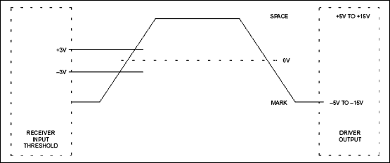
The TIA/EIA-232-F specification says that the receiver threshold must be between +/-3V. In a perfect world, this means that the transmitters must swing a minimum of +/-3V. However, this leaves a 0V noise margin. Any noise that gets coupled onto the line could cause errors in the data. Therefore, the RS-232 specification says that the transmitters must swing a minimum of +/-5V. This gives the system a very robust 2V minimum-noise margin. But, at the same time, this minimum requirement makes the specification impossible to meet in a +/-5V-powered system without additional power-supply converters. If, for example, the 5V power supply were actually 5% low (4.75V), an ideal transmitter would be able to swing only as high as 4.75V. Although this swing isn't truly RS-232-compliant, it is more than enough to work properly with an RS-232-compliant receiver. In other words, this theoretical part would be RS-232-compatible but not RS-232-compliant.This distinction is important, because an RS-232-compatible, but not RS-232-compliant, part can be powered from +/-5V supplies without the need for charge pumps. Without the charge pumps, the part becomes smaller and cheaper. This is exactly the case with the MAX3314E. The MAX3314E works off +/-5V +/-5% supplies, guaranteeing +/-3.7V swings when fully loaded. This swing is enough to properly drive all RS-232-compliant receivers, but reduces the noise margin from 2V to .7V. Designers who are considering making this compromise must carefully weigh the advantages of smaller size and lower cost against this reduced-noise margin and the fact that their system will not be truly RS-232-compliant.

Figure 11. The MAX3314E runs off of +/-5V supplies, but does not have charge-pump doublers and inverters. This makes the part smaller, cheaper, and RS-232-compatible, but not RS-232-compliant.
Another interesting Maxim part is the MAX3316. This part approaches the situation in another direction. It is designed to run in systems that are powered from 2.25V to 3.0V. Previously, the only Maxim solutions available for this supply range were the inductor-based parts, such as the MAX3218. Inductor-based solutions work great and are RS-232-compliant, but tend to be a bit bulkier and slightly more expensive than their capacitor counterparts. The MAX3316 provides a capacitor-based solution, at the expense of being RS-232-compatible and not RS-232-compliant. It works exactly as the 3.0V to 5V parts, except its charge pumps are designed to work down to 2.25V. With these low supply voltages, the part is unable to guarantee RS-232-compliant output swings, but can ensure RS-232-compatible outputs of +/-3.7V.
___________________________
*This designates an active low signal; the line above the text in the figures means the same thing.
 電子發燒友App








評論