Abstract: Features are described for Maxim's large selection of RS-485 transceivers. Devices are identified to meet requirements for half- or full-duplex operation, supply voltages down to 2.5V, ESD protection up to ±15kV, data rates from 250kbps to 12Mbps, slew-rate limited devices for low radiated noise operation, fail-safe operation with open or shorted cables, normal 1 unit-load to 1/8 unit-load for expanded networks, and low-power shutdown operation.
Maxim makes what seems like a bewildering array of RS-485 drivers and receivers. This application note explains the different features within Maxim's product line and thus will help you in selecting the most appropriate part for your needs. Below are explanations of the various features and other important things to keep in mind.
Although it is true that fast devices can be used for both high data rates and low data rates, there are drawbacks in using devices that are faster than needed, including higher radiated emissions and greater susceptibility to improper terminations.
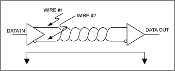
Radiated emissions occur because the wiring used in RS-485 will act as an antenna. RS-485 tries to minimize radiated emissions by using twisted-pair cabling and balanced transmitters. The idea behind this is that the balanced transmitter, as the name implies, will generate two equal but opposite signals that are sent down the two wires in a twisted pair. Because the wires are virtually on top of each other, they will tend to radiate the exact opposite signal that the other wire is transmitting. This has the effect of canceling each other out, and ideally results in no net radiated emissions. This tends to work fairly well, but, like everything in engineering, it isn't perfect. Inevitably, some radiated emissions will leak out. As a general rule, the higher the frequency components in the signal and the longer the cable, the worse the situation becomes.
The same applies to cable terminations. Because of the distances of the cabling and the data rates, careful attention must be paid to transmission-line effects. Both ends of an RS-485 cable should be properly terminated in the characteristic impedance of the cable to prevent reflections. Resistor and cable tolerances, among other things, can result in mismatches between these two impedances. This will result in reflections that reduce the noise margins and can ultimately cause loss of data. Similar to radiated emissions, the higher the frequency components sent down the cable and the longer the cable, the more likely it is that reflections will affect your system.
Slew-rate limiting can help low-speed systems with both of the problems mentioned above. Slew-rate limiting works by slowing the edges of the RS-485 signal down and therefore reducing the signal's high-frequency components. Compare the plots in Figures 1 and 2.

Figure 1. Driver output waveform and FFT plot of a MAX3485E transmitting a 125kHz (250kbps) signal (a); driver output waveform and FFT plot of a MAX3483E transmitting a 125kHz (250kbps) signal (b).
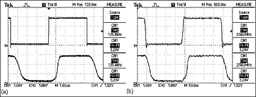
Figure 2. A close-up of the time domain plots comparing the MAX3483 and the MAX3485 transmitting at 125kHz (250kbps) (a); a close-up of the time domain plots comparing the MAX3486 and the MAX3485 transmitting at 1.25MHz (2.5Mbps) (b).
In Figure 1, both a and b show RS-485 signals transmitting at 250kbps (125kHz). Figure 1a was taken using a MAX3485E that is not slew-rate limited and is capable of speeds up to 12Mbps. Figure 1b was taken with the slew-rate limited MAX3483E that has a maximum data rate of 250kbps. In Figure 1a, the Fourier transform shows frequency components well past 2Mbps. These high-frequency components are necessary to produce the nice square edges needed for higher data rates. The Fourier transform of the slew-rate-limited part shows that the frequency components above 2MHz are virtually gone. With these higher-frequency components gone from the signal, a system designed around slew-rate-limited parts will tend to radiate less and will be less susceptible to mismatches in terminations.
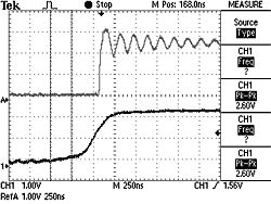
Figure 3. A comparison of the rising edges on a MAX3486 (top, not slew-rate limited) and a MAX3483 (bottom, slew-rate limited) using a 120-ohm impedance cable, improperly terminated with 220 ohms.
Table 1 compares three different RS-485 parts. The MAX3485 is the fastest in the family and is capable of up to 12Mbps. The MAX3483 is slew-rate limited and will work to 250kbps. The MAX3486 is a compromise between the two at a maximum speed of 2.5Mbps.
Table 1. Comparison of the Part That Is Not Slew-Rate Limited, the MAX3485, with Two Parts That Have Varying Degrees of Slew-Rate Limiting, the MAX3483 and the MAX3486
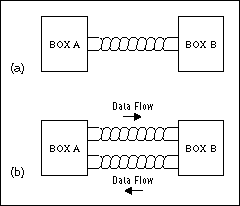
Figure 4. Half-duplex RS-485 system (a); full-duplex RS-485 system. (b)
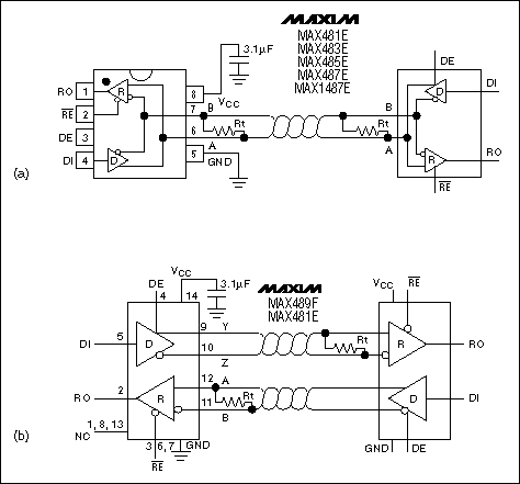
Figure 5. A half-duplex part as used in a system (a); a full-duplex part as used in a system.
Because the half-duplex part must be able to transmit and receive on the same twisted pair, the output pins of the transmitter and the input pins to the receiver are tied together. The full-duplex part has the transmitter and the receiver separated. In addition, the half-duplex part will always have a driver-enable (DE in the figure) pin. This is required because the transmitter must be tri-stated while receiving data. Full-duplex parts may or may not have a driver-enable pin, depending on whether or not it is designed for a multidrop system.
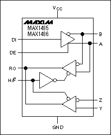
Figure 6. The MAX1485/MAX1486 can be configured as a full-duplex part or a half-duplex part.
One special part to note is the MAX3471. This part is fully specified for operation from 2.5V to 5.5V. Thus, the MAX3471 is especially interesting in battery-powered systems. For example, a system using 3AA batteries will have a typical operating voltage range of 4.5V when the batteries are new, down to 2.7V when the batteries are about dead. The MAX3471's wide operating range allows the part to operate directly from the batteries without any power-supply converters that can increase system cost.
Table 2. Examples of Maxim Parts That Can Be Used vs. Supply-Voltage Range
Ultimately, up to 32 unit loads can be connected to a single twisted pair. These 32 unit loads can be any combination of parts. For example, 32 x 1/4 unit-load parts plus 16 x 1 unit-load parts can be successfully used in a system. At the present time, Maxim makes devices that are 1 unit load, 1/4 unit load, and 1/8 unit load. Examples of each are shown in the table below.
Table 3. Comparison of Three Maxim Parts with Different Unit Loads
Table 4. The Level of ESD Protection on Maxim's Standard RS-485 Parts vs. the ±15kV Protected Parts
ESD levels were measured using the human body and IEC1000-4-2 method.
The four common faults that an RS-485 system can experience are as follows:
References
Maxim makes what seems like a bewildering array of RS-485 drivers and receivers. This application note explains the different features within Maxim's product line and thus will help you in selecting the most appropriate part for your needs. Below are explanations of the various features and other important things to keep in mind.
Data Rates and Slew-Rate Limiting
At some time during the design of an RS-485 system, a maximum data rate appropriate for that system is determined. Then it becomes necessary to choose the physical RS-485 devices that are capable of running at this speed. Devices are selected that are rated for speeds equal to or greater than the required data rate. Knowing this, you might wonder if there are any disadvantages in choosing the fastest devices available, if they might be overkill. The answer is yes!Although it is true that fast devices can be used for both high data rates and low data rates, there are drawbacks in using devices that are faster than needed, including higher radiated emissions and greater susceptibility to improper terminations.
Radiated emissions occur because the wiring used in RS-485 will act as an antenna. RS-485 tries to minimize radiated emissions by using twisted-pair cabling and balanced transmitters. The idea behind this is that the balanced transmitter, as the name implies, will generate two equal but opposite signals that are sent down the two wires in a twisted pair. Because the wires are virtually on top of each other, they will tend to radiate the exact opposite signal that the other wire is transmitting. This has the effect of canceling each other out, and ideally results in no net radiated emissions. This tends to work fairly well, but, like everything in engineering, it isn't perfect. Inevitably, some radiated emissions will leak out. As a general rule, the higher the frequency components in the signal and the longer the cable, the worse the situation becomes.
The same applies to cable terminations. Because of the distances of the cabling and the data rates, careful attention must be paid to transmission-line effects. Both ends of an RS-485 cable should be properly terminated in the characteristic impedance of the cable to prevent reflections. Resistor and cable tolerances, among other things, can result in mismatches between these two impedances. This will result in reflections that reduce the noise margins and can ultimately cause loss of data. Similar to radiated emissions, the higher the frequency components sent down the cable and the longer the cable, the more likely it is that reflections will affect your system.
Slew-rate limiting can help low-speed systems with both of the problems mentioned above. Slew-rate limiting works by slowing the edges of the RS-485 signal down and therefore reducing the signal's high-frequency components. Compare the plots in Figures 1 and 2.

Figure 1. Driver output waveform and FFT plot of a MAX3485E transmitting a 125kHz (250kbps) signal (a); driver output waveform and FFT plot of a MAX3483E transmitting a 125kHz (250kbps) signal (b).

Figure 2. A close-up of the time domain plots comparing the MAX3483 and the MAX3485 transmitting at 125kHz (250kbps) (a); a close-up of the time domain plots comparing the MAX3486 and the MAX3485 transmitting at 1.25MHz (2.5Mbps) (b).
In Figure 1, both a and b show RS-485 signals transmitting at 250kbps (125kHz). Figure 1a was taken using a MAX3485E that is not slew-rate limited and is capable of speeds up to 12Mbps. Figure 1b was taken with the slew-rate limited MAX3483E that has a maximum data rate of 250kbps. In Figure 1a, the Fourier transform shows frequency components well past 2Mbps. These high-frequency components are necessary to produce the nice square edges needed for higher data rates. The Fourier transform of the slew-rate-limited part shows that the frequency components above 2MHz are virtually gone. With these higher-frequency components gone from the signal, a system designed around slew-rate-limited parts will tend to radiate less and will be less susceptible to mismatches in terminations.

Figure 3. A comparison of the rising edges on a MAX3486 (top, not slew-rate limited) and a MAX3483 (bottom, slew-rate limited) using a 120-ohm impedance cable, improperly terminated with 220 ohms.
Table 1 compares three different RS-485 parts. The MAX3485 is the fastest in the family and is capable of up to 12Mbps. The MAX3483 is slew-rate limited and will work to 250kbps. The MAX3486 is a compromise between the two at a maximum speed of 2.5Mbps.
Table 1. Comparison of the Part That Is Not Slew-Rate Limited, the MAX3485, with Two Parts That Have Varying Degrees of Slew-Rate Limiting, the MAX3483 and the MAX3486
| ? | MAX3483 | MAX3485 | MAX3486 |
| Maximum data rate | .25Mbps | 12Mbps | 2.5Mbps |
| Transition time | 1200nS max | 25nS max | 60nS max |
| Propagation delay | 1500nS max | 35nS max | 70nS max |
Full/Half Duplex
RS-485 is designed in such a way that only one transmitter on a twisted pair can be active at a time. With this constraint, in the system shown in Figure 4a, Box A can transmit data to Box B or Box B can transmit data to Box A, but both can't transmit data at the same time. This is referred to as "half duplex." A full-duplex system, on the other hand, would allow communications in both directions simultaneously. Full-duplex systems can be designed using RS-485, but require two twisted-pair cables running between nodes, as shown in Figure 4b. One twisted pair is dedicated to transmitting information in one direction, and the other twisted pair is dedicated to transmitting data in the opposite direction. Each system requires slightly different physical devices. Figure 5a shows a typical half-duplex part, and Figure 5b shows a typical full-duplex part.
Figure 4. Half-duplex RS-485 system (a); full-duplex RS-485 system. (b)

Figure 5. A half-duplex part as used in a system (a); a full-duplex part as used in a system.
Because the half-duplex part must be able to transmit and receive on the same twisted pair, the output pins of the transmitter and the input pins to the receiver are tied together. The full-duplex part has the transmitter and the receiver separated. In addition, the half-duplex part will always have a driver-enable (DE in the figure) pin. This is required because the transmitter must be tri-stated while receiving data. Full-duplex parts may or may not have a driver-enable pin, depending on whether or not it is designed for a multidrop system.
Software Selectable
As of January 1, 2001, Maxim will be making three parts that can run either full or half duplex. These are the MAX1485, the MAX1486, and the MAX3089. This can be valuable in systems that may need to connect to both full-duplex and half-duplex systems. Figure 6 shows the MAX1485. Note the pin labeled H/F*. When this pin is pulled low, the half-duplex receiver is disabled; when it is pulled high, the full-duplex receiver is disabled.
Figure 6. The MAX1485/MAX1486 can be configured as a full-duplex part or a half-duplex part.
2.5V/3.3V and 5V Power Supplies
According to the EIA/TIA 485 Rev A specification, an RS-485 transmitter must have a differential output voltage of between 1.5V and 5V when loaded with 27 ohms. With careful design and low dropout transmitters, this is attainable with power supplies running as low as 2.5V. Therefore, systems running from solely a 3.0V to 3.6V power supply can use Maxim's 3V family of parts and remain compliant with the RS-485 specification.One special part to note is the MAX3471. This part is fully specified for operation from 2.5V to 5.5V. Thus, the MAX3471 is especially interesting in battery-powered systems. For example, a system using 3AA batteries will have a typical operating voltage range of 4.5V when the batteries are new, down to 2.7V when the batteries are about dead. The MAX3471's wide operating range allows the part to operate directly from the batteries without any power-supply converters that can increase system cost.
Table 2. Examples of Maxim Parts That Can Be Used vs. Supply-Voltage Range
| Examples of Parts | Power-Supply Voltage |
| MAX3483E Family | 3.0V to 3.6V |
| MAX3080 Family | 4.75V to 5.25V |
| MAX3471 | 2.5V to 5.5V |
1 Unit Load, 1/4 Unit Load, 1/8 Unit Load
"Unit loads" are a hypothetical unit created by the EIA 485 specification to help designers of RS-485 systems determine how many receivers/transmitters can be connected to each cable. The specification recognizes that the number of devices that can be connected depends heavily on how much each part loads the system down. The more a part loads the system down, the fewer the parts that can be used. In order to quantify this, the "unit load" was invented. All RS-485 parts should characterize their loading in terms of fractions or multiples of these unit loads. For example, a MAX487 is characterized as a 1/4 unit-load part, whereas the MAX3485 is characterized as a 1 unit-load part. This basically means that the MAX487 will load a system down 1/4 as much as a MAX3487, and therefore up to four times as many MAX487s can be connected to a system if the system solely used MAX3487s.Ultimately, up to 32 unit loads can be connected to a single twisted pair. These 32 unit loads can be any combination of parts. For example, 32 x 1/4 unit-load parts plus 16 x 1 unit-load parts can be successfully used in a system. At the present time, Maxim makes devices that are 1 unit load, 1/4 unit load, and 1/8 unit load. Examples of each are shown in the table below.
Table 3. Comparison of Three Maxim Parts with Different Unit Loads
| ? | MAX3485 | MAX487 | MAX3085 |
| Maximum number of tx/rec per twisted pair | 32 | 128 | 256 |
| Unit loads | 1 | 1/4 | 1/8 |
High ESD Protection
All Maxim devices incorporate ESD-protected structures on each pin to protect against electrostatic discharges encountered during handling and assembly. Maxim's standard RS-485 parts offer ≥ 2kV ESD on all their pins. Maxim's ±15kV protected parts improve upon this by offering (as one might suspect) ±15kV protection on their driver outputs and receiver inputs. Everything in life has a price, and the added ESD protection comes at a small additional cost. The ±15kV protected parts are usually the same pin out and functionality as the standard parts, allowing these parts to be easily substituted without modification to the board layout. The MAX485 and the MAX485E are examples of two such parts. The MAX485 has the standard level of protection, whereas the MAX485E has the ±15kV protection. It is important to note how our parts respond during ESD strikes. Not only will the parts not be damaged by ESD strikes less than their rated value, but they will also continue to work normally without having to recycle power. In addition, they are protected against ESD strikes while powered up, powered down, and in shutdown.Table 4. The Level of ESD Protection on Maxim's Standard RS-485 Parts vs. the ±15kV Protected Parts
ESD levels were measured using the human body and IEC1000-4-2 method.
| ? | Standard Maxim RS-485 Parts | ±15kV Protected Parts |
| Driver output and receiver input pins | ≥ ±2kV | ≥ ±15kV |
| All other pins | ≥ ±2kV | ≥ ±2kV |
Fail-Safe Operation
Four common fault conditions can occur in an RS-485 system that can cause erroneous data. By having a specially designed input stage, Maxim's fail-safe parts are designed to prevent erroneous data in these conditions.The four common faults that an RS-485 system can experience are as follows:
- All transmitters in a system are in shutdown.
- The receiver is not connected to the cable.
- The cable has an open.
- The cable has a short.
Shutdown
The sole purpose of the shutdown feature is to save power. Putting a part into shutdown significantly lessens its supply current, thus reducing power consumption. An example of the power savings can be illustrated using the MAX3483. During normal operation, the typical supply current is 1.1mA. When in shutdown, the supply current is reduced to 2nA! One important aspect to consider when using shutdown is the time it takes to go from a shutdown state to a valid output. In the case of the MAX3483, this can take as long as 3μS. The MAX3485 reduces this time to 900nS in the worst case.References
- TIA/EIA-485-A Electrical Characteristics of Generators and Receivers for Use in Balanced Digital Multipoint Systems
- TSB89 Application Guidelines for TIA/EIA-485-A
 電子發燒友App










評論