Abstract: Rail splitting is creating an artificial virtual ground as a reference voltage. It is used to set the signal to match the op amp's "sweet spot." An op amp has the most linear- and distortion-free qualities at that sweet spot. Typically, the sweet spot occurs near the center between the single power rail and ground. In the case of a number of signals, the virtual ground can control channel DC errors when multiplexing or switching the signals.
"Rail Splitter" was the nickname of U.S. President Abraham Lincoln. The name came from his humble background—as a young man, he split lumber for fence rails. About as close as most of us have come to working with lumber is playing with Lincoln Logs? toys. Those were little brown round notched pieces of wood that we used to build log cabin style buildings. Because Mr. Lincoln was born in a log cabin, the logs were also named for him. He is also the only U.S. President that holds a U.S. Patent (#6469).
Though interesting, this is not the kind of rail splitting we are discussing. In electronic circuits, the rails are the common power supply and ground connections to all of the components. Many components, such as amplifiers and analog-to-digital converters (ADC), require that the signal is biased in order to center it midway between the rails. This is a virtual ground point, and is also nicknamed a "Rail Splitter." In earlier electronic circuits, there were both positive and negative power supplies, so signal biasing was easy—we just used ground as the reference. Typical modern circuits utilize only one power supply. For example, if we only have a +5V rail and ground, we may need a center bias point (virtual ground) at 2.5V. If we only need one imprecise bias point, two 5% resistors will do, as shown in Figure 1a. If the bias point is critical, Figure 1b shows that the resistors can be replaced and be used with any one of the MAX5490/MAX5491/MAX5492 precision resistor dividers to give us an accuracy of 0.035% with a 1ppm/°C temperature coefficient.
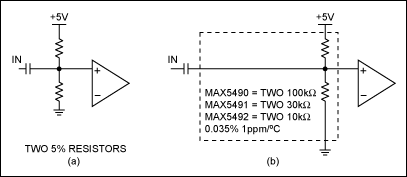
Figure 1. Setting a midrange bias point.
In the application illustrated in Figure 2 we want to match the DC voltage between channels to minimize the settling time after a switch point. For this application, we need multiple matching bias points.
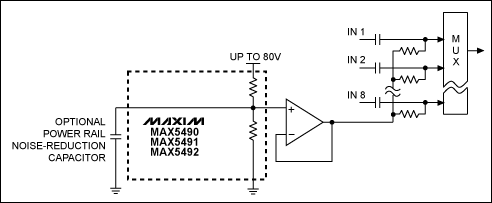
Figure 2. A multiple precision-matched bias supply.
In the case where the MAX5490/MAX5491/MAX5492 are not required to have 0.035% precision, we can suggest using the circuit shown in Figure 3. In this circuit, only 1% precision is necessary, but it is still important that all the bias points are the same.
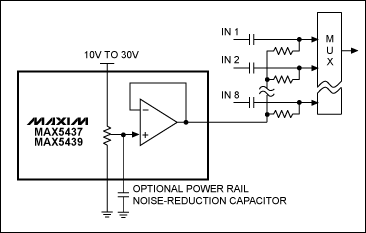
Figure 3. An integrated virtual ground rail splitter.
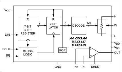
The MAX5437/MAX5439 are 128-step digital potentiometers with an uncommitted op amp, as seen in Figure 4. If we ignore the three SPI? serial port pins by grounding them, the MAX5437/MAX5439 will power up at midscale with ±1% tolerance. The MAX5437 has a 50kΩ end-to-end resistance, while the MAX5439 is 100kΩ end to end. They both are available in a 14-pin TSSOP package.
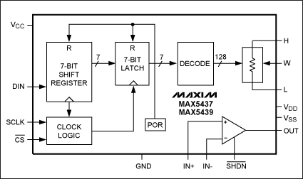
Figure 4. The MAX5437 and MAX5439 digital potentiometers.
The MAX5437 and the MAX5439 each makes a very versatile virtual ground. If we have a known asymmetrical signal waveform, we can change the pot position, and the DC bias voltage can then be any one of 128 different levels. If we want the voltage steps to be smaller (more precise), we can add resistors on the top and bottom of the pot, moving the 128 steps into a smaller range. Another alternative is to use a voltage reference to set the pot end voltages.
Because the MAX5437/MAX5439 op amps are uncommitted, we have the option of adjusting gains and offsets, providing inversion, and even building filters. The MAX5437/MAX5439 can be powered from ±15V. In addition, these op amps have a shutdown function pin, which means that the output can be used to multiplex several parts together. In a system where the ADC requires a dither signal to be added to the signal, we can add the dither signal also. By injecting the dither signal into Figure 3, where the noise reduction capacitor ground is drawn, we automatically apply the dither to all the multiplexer inputs. Because the MAX5437/MAX5439 switch in a glitchless manner, the pot may be moved between taps at will. And best of all, the temperature coefficient is only 5ppm/°C ratiometric.
Our rail splitter is versatile, as was Mr. Lincoln, but times have changed in the last 160 years. Today, Mr. Lincoln would be amazed with our fast world. We have fast communication for all ages by Internet and telephone, fast food, instant coffee, fast cars, fruit in winter (flown in from the southern hemisphere), and sometimes microwave ovens even seem to take too long. The strange thing is that Mr. Lincoln's patent was applied for and then granted in only 73 days, whereas today's patent processing takes years. His patent was three pages; today it is difficult to find patents with less than ten pages, and some are even hundreds of pages long. So much for speed, progress, and the much touted paperless office! In our ever-changing electronic virtual ground, however, the rail splitter is a progressive tool that design engineers can use to further improve our lifestyle in this fast world.
|
|
Though interesting, this is not the kind of rail splitting we are discussing. In electronic circuits, the rails are the common power supply and ground connections to all of the components. Many components, such as amplifiers and analog-to-digital converters (ADC), require that the signal is biased in order to center it midway between the rails. This is a virtual ground point, and is also nicknamed a "Rail Splitter." In earlier electronic circuits, there were both positive and negative power supplies, so signal biasing was easy—we just used ground as the reference. Typical modern circuits utilize only one power supply. For example, if we only have a +5V rail and ground, we may need a center bias point (virtual ground) at 2.5V. If we only need one imprecise bias point, two 5% resistors will do, as shown in Figure 1a. If the bias point is critical, Figure 1b shows that the resistors can be replaced and be used with any one of the MAX5490/MAX5491/MAX5492 precision resistor dividers to give us an accuracy of 0.035% with a 1ppm/°C temperature coefficient.

Figure 1. Setting a midrange bias point.
In the application illustrated in Figure 2 we want to match the DC voltage between channels to minimize the settling time after a switch point. For this application, we need multiple matching bias points.

Figure 2. A multiple precision-matched bias supply.
In the case where the MAX5490/MAX5491/MAX5492 are not required to have 0.035% precision, we can suggest using the circuit shown in Figure 3. In this circuit, only 1% precision is necessary, but it is still important that all the bias points are the same.

Figure 3. An integrated virtual ground rail splitter.
The MAX5437/MAX5439 are 128-step digital potentiometers with an uncommitted op amp, as seen in Figure 4. If we ignore the three SPI? serial port pins by grounding them, the MAX5437/MAX5439 will power up at midscale with ±1% tolerance. The MAX5437 has a 50kΩ end-to-end resistance, while the MAX5439 is 100kΩ end to end. They both are available in a 14-pin TSSOP package.

Figure 4. The MAX5437 and MAX5439 digital potentiometers.
The MAX5437 and the MAX5439 each makes a very versatile virtual ground. If we have a known asymmetrical signal waveform, we can change the pot position, and the DC bias voltage can then be any one of 128 different levels. If we want the voltage steps to be smaller (more precise), we can add resistors on the top and bottom of the pot, moving the 128 steps into a smaller range. Another alternative is to use a voltage reference to set the pot end voltages.
Because the MAX5437/MAX5439 op amps are uncommitted, we have the option of adjusting gains and offsets, providing inversion, and even building filters. The MAX5437/MAX5439 can be powered from ±15V. In addition, these op amps have a shutdown function pin, which means that the output can be used to multiplex several parts together. In a system where the ADC requires a dither signal to be added to the signal, we can add the dither signal also. By injecting the dither signal into Figure 3, where the noise reduction capacitor ground is drawn, we automatically apply the dither to all the multiplexer inputs. Because the MAX5437/MAX5439 switch in a glitchless manner, the pot may be moved between taps at will. And best of all, the temperature coefficient is only 5ppm/°C ratiometric.
Our rail splitter is versatile, as was Mr. Lincoln, but times have changed in the last 160 years. Today, Mr. Lincoln would be amazed with our fast world. We have fast communication for all ages by Internet and telephone, fast food, instant coffee, fast cars, fruit in winter (flown in from the southern hemisphere), and sometimes microwave ovens even seem to take too long. The strange thing is that Mr. Lincoln's patent was applied for and then granted in only 73 days, whereas today's patent processing takes years. His patent was three pages; today it is difficult to find patents with less than ten pages, and some are even hundreds of pages long. So much for speed, progress, and the much touted paperless office! In our ever-changing electronic virtual ground, however, the rail splitter is a progressive tool that design engineers can use to further improve our lifestyle in this fast world.
Lincoln Logs is a registered trademark of Playskool Manufacturing Company.
SPI is a trademark of Motorola, Inc.
 電子發燒友App





評論