| Abstract: To understand how common-mode signals are created and then suppressed, you should first understand the interaction of shields and grounds in common cable configurations. The following discussion defines a common-mode signal, reviews the common cable configurations, considers shielded vs. unshielded cables, and describes typical grounding practices. The article discusses methods whereby common-mode signals are created and rejected.
The primary focus of this discussion is on RS-485/RS-422 cables and signals, but the discussion also applies to telephone, audio, video, and computer-network signals.
Common-Mode Signals DefinedWhen referenced to the local common or ground, a common-mode signal appears on both lines of a 2-wire cable, in-phase and with equal amplitudes. Clearly, a common-mode signal cannot be present if one of the lines is connected to local common. Technically, a common-mode voltage is one-half the vector sum of the voltages from each conductor of a balanced circuit to local ground or common. Such signals can arise from one or more of the following sources:
Further details about these basic conditions appear in a later section. Before examining those details, however, it is useful to understand different cable configurations, signal-grounding conventions, and shield-grounding practices. General Data-Transmission SystemThe principal aim of any data-transmission system is to send data from one location to another, whether within a single box or enclosure, between boxes within an enclosure, between enclosures within a building or defined area, or between buildings. Figure 1 illustrates an RS-485 signaling situation in which the buildings are supplied from different power circuits.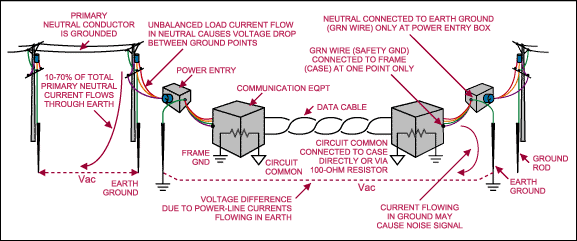 Figure 1. This generalized system transmits data between two widely separated buildings, and shows the earth currents created between ground points in a single-phase power-distribution system. Similar currents are created in 3-phase, Y-connected systems. Bonding a power-line subscriber's neutral line to a ground rod sunk in the earth at the power-entry point establishes the power-line neutral as a safety ground. From that point, a bare or green-insulated wire carries the safety-ground reference to all electrical outlets and installed equipment throughout the premises. Industrial chassis frames are bonded to the safety ground at the chassis' power-input point, where it becomes frame ground. Circuit common is often connected to the chassis at one or more points, but a single ground point per chassis is best. In some cases, the circuit common might be isolated from the frame ground. Leakage currents that flow in the safety-ground wire from machine windings to the case, or more commonly, that flow between the ground and earth due to AC primary or secondary neutral currents in the power-distribution system, can produce a potential difference between the neutral and frame ground. Ground differentials can vary from several volts to several tens of volts. The greatest differentials are found in single-phase or 3-phase Y-distribution systems, in which the portion of neutral current flowing in the earth can be 10% to 70% of the total neutral current flowing in the primary circuit. Voltage measurements between ground points are typically 0.2VRMS to 5VRMS, and (rarely) as high as 65VRMS between widely separated grounds. Cables and NoiseNoise signals can appear in a cable for several reasons: capacitive coupling of nearby electric fields (E); inductive coupling of local magnetic fields (M); electromagnetic coupling of radio signals in space (EM); and conduction through intentional or sneak circuit paths (C). The coupled signal appears as an additional signal in series with the line or lines (Figure 2). Table 2 lists the type and origin of potential noise sources in cables. Twisted-pair lines intercept coupled signals equally, so the incident signals appear only as common-mode signals. Twisted-pair lines are said to be balanced if the impedances connected from each line to the local common are identical.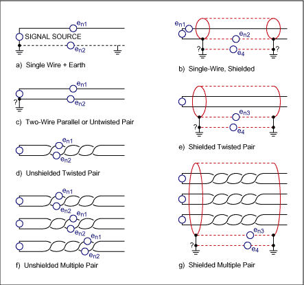 Figure 2. These transmission-cable configurations show the locations of possible noise sources. Table 1. Electrical Cable Types and Applications
Table 2. Noise Sources for Listed Cable Configurations
Circuit and Shield GroundingSingle line with earth return: The signal common line connects to earth ground at the source and load by the earth (frame) return path. Circuit commons must also be connected to the earth (frame) ground.Single-wire shielded: Signal current is always carried on the shield, so connections to the circuit common must be present at both source and load. Table 3 lists the shield-grounding connections for various conditions. Table 3. Shield Grounding for Single-Wire Shielded Cables
Two-wire parallel: Each conductor carries an equal amount of signal current, but in opposite directions. Table 4 lists line-grounding connections for various conditions. Table 4. Line Grounding for Two-Wire Parallel Cables
Unshielded twisted pair(s): Any driving or receiving circuit probably includes a connection to local common or frame ground, but connecting the transmission line itself to frame ground is unnecessary and undesirable. A differential-mode or balanced-signal source (such as unshielded RS-422 and RS-485 data-transmission circuits) transmits data signals to a remote location where source and load circuits are both referenced to local ground or common. Transformer-coupled applications include 10/100 Base-T Ethernet cables. Shielded twisted pair(s): Grounding the shield of any shielded pair shunts to ground any unwanted signals or noise intercepted by the shield. Typical shield materials (copper and aluminum) shield the internal conductors from signals coupled capacitively or electromagnetically, but not from those coupled inductively. For any shielded pair(s) carrying balanced signals, you should connect the shield to ground at one end, usually the receiving end. If the transmitting-location ground carries a noise signal different from that at the receiving location, grounding the shield at both ends causes current flow along the shield. Grounding at both ends is acceptable if there is no substantial potential difference between the two ground locations. This configuration includes shielded RS-422 and RS-485 data-transmission circuits. RS-485 Application Guidelines specify connecting the shield to earth ground, either directly or through a fusible resistor at one or both ends of the cable shield. Signal-Mode DefinitionsElectrical signals carried on cables can be described as normal mode, differential mode, or common mode.
Figure 3 shows a 3V differential-mode signal riding on a 2.5V common-mode signal. The DC offset is typical of differential-mode data transmitters operating from a single supply. The common-mode voltage can be AC, DC, or a combination of AC and DC. (Figure 3 represents the simplest case, a DC common-mode voltage with no AC component.) 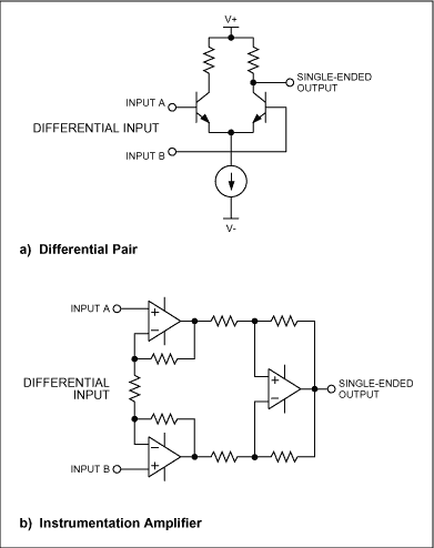 Figure 3. Typical RS-485 transmitters generate a common-mode DC offset voltage as shown. When cables are long (as RS-485 data cables can be), the originating signal's common or ground may not have the same electrical potential as that of the receiving location. The RS-485 specification says to connect the drive-circuit common to frame ground, either directly or through a 100 resistor. The result is illustrated in Figure 4. 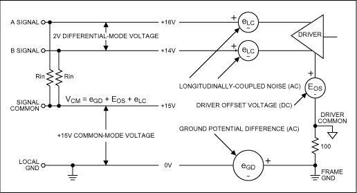 Figure 4. Three types of common-mode signal (eGD, eLC, and EOS) can be present in a 2-wire data-transmission system. Signal common can assume a common-mode voltage equal to the vector sum of the ground-potential difference, the driver-offset voltage, and any longitudinally coupled noise voltage generated along the signal path between transmitter and receiver:  The Origin of Common-Mode SignalsThree sources of common-mode voltage are represented in Figure 4 as eGD, eLC, and EOS:
Minimizing Common-Mode SignalsEOS can be made quite small, or even zero, by operating a differential-mode driver from balanced supplies. In contrast, eGD can be minimized only by maintaining a relatively short distance between the transmitting and receiving locations. eLC can be minimized by using a shielded twisted pair: noise introduced within the cable arises equally on each of two tightly twisted wires. Otherwise, a normal-mode signal would be present due to the line's asymmetry with respect to disturbing fields.The load must also be symmetrical; the resistive and capacitive load impedances on both lines of the twisted pair must be matched. Inductively coupled signals can be prevented only by using magnetic shielding. (Note that any wire carrying signal current is a source of magnetic radiation.) Suppressing Common-Mode SignalsCommon-mode signals (VCM) must be rejected in the receiving circuit. That rejection is easily accomplished when the receiving circuit is passive (headphones or loudspeaker), transformer coupled, isolated and battery operated, or otherwise not referenced in any way to the transmitting-circuit common (either capacitively or resistively connected). The configurations noted here are inherently immune to common-mode signals, but receiving circuits referenced to the transmitting-circuit common must be designed to accept the full range of VCM presented to them. All such designs involve differential receivers with high common-mode-rejection (CMR). If the VCM is of relatively low amplitude, a high-CMR receiver alone may be adequate.How High-CMR Receivers WorkAll high-CMR receivers employ either some form of differential pair, or a traditional instrumentation amplifier consisting of three amplifiers, as indicated in Figure 5. Each amplifier accepts a differential input in the presence of a limited common-mode voltage, with an acceptable VCM limited to somewhat less than the supply voltages. Such circuits can handle analog and digital signals. Figure 5. These differential-amplifier circuits exhibit high common-mode rejection. Additional isolation must be employed if VCM is to exceed the receiver's common-mode range. Most such circuits employ a transformer-coupled isolated supply, plus any one of the following:
All the techniques shown in Figure 6 can couple a signal across the isolation barrier in the presence of high values of VCM. Each depends on the use of an isolated power supply, which is usually transformer coupled. Isolation voltage limits are determined by the transformer and by the type of isolation chosen. Isolation to 2500V or more is practical with transformer-, optical-, and capacitive-coupling techniques; resistive coupling is usually limited to the range of 50V to 100V. 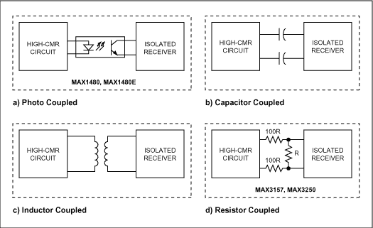 Figure 6. The isolation techniques and typical components shown achieve high common-mode-signal rejection. Resistive coupling involves transferring data across a resistive attenuator, which attenuates both the data and the common-mode signals. Thus, resistive isolation is limited by the fraction of VCM that can be accommodated by the receiving circuit, while reliably detecting a small fraction of the original data signal. In Figure 6, the various isolation drivers treat the requirement for isolated power in different ways. Today's inductively-coupled devices make no provision for the power supply, and therefore require external isolated supplies. Some capacitor-coupled devices include transformer drivers, but they require external transformers. Maxim's MAX3157 and MAX3250 drivers contain isolated supplies and require external, low-profile, ceramic charge-pump capacitors. Members of the MAX1480 and MAX1480E families, however, contain fully isolated supplies including transformers. Thus, you can choose the cable type and isolation technology intelligently, once the source and magnitude of an intruding common-mode signal is known. You need only measure or calculate the magnitude of the disturbing signals, and then select your components to meet the overall requirements of the system. References
|
Understanding Common-Mode Sign
- signal(24749)
相關推薦
16位高性能隔離數據采集(DAQ)解決方案
input signals (up to ±12 V) superimposed on large common-mode offsets (tested up to 155 Vp-p from
2018-12-24 15:10:38
Common Mode Inductors forEMI Filters Require Careful Attention to Core Materi
Switching power supplies generatetwo types of noise: common modeand differential mode
2009-10-10 16:18:57
Sign-Magnitude Drive符號震級驅動
Sign-Magnitude Drive符號震級驅動Introduction引言In this article I’ll talk about one of the popular
2021-09-13 07:37:21
common.c程序里TMOD |= 0x20是不是應該是timer 1 mode2呢?
請問我在common.c裡面看到下面的程序, TMOD |= 0x20是不是應該是timer 1 mode2呢?
void InitialUART0_Timer1_Type1(UINT32
2023-09-01 07:59:17
APA320音頻功放芯片
settings of nominally 23.8 dB, 29.8 dB, 33.3 dBand35.8 dB? Differential inputs minimize common-mode
2022-05-17 14:53:06
Protect Current-Sense Amplifiers from Negative Overvoltage
voltage proportional to the current in that resistor. The sense-voltage rides on a common-mode
2011-08-21 16:49:34
USB-C DFP、5V/3A 輸出、通用交流輸入參考設計包括BOM及原理圖
84% average efficiencyNo optocoupler or TL431Passes Class B conducted emissions without a common-mode choke
2018-09-06 09:07:38
使用負電源輸入的模擬前端驅動器放大器包括BOM及層圖
主要特色Negative rail input (NRI), rail-to-rail output (RRO)Wide output common-mode control rangeLow
2018-09-27 08:47:43
具有交流和直流耦合型固定增益放大器的 16 位 1GSPS 數字轉換器技術資料下載
device. Different options for common-mode voltages, power supplies, and interfaces are discussed
2018-07-13 00:50:56
單+5V電源供電AD8041接成緩沖器,輸入電壓范圍是多少?
電圧范圍為-0.7V~+5.7V。看手冊,單+5V電源供電的AD8041其輸入共模電壓范圍(Input Common-Mode Voltage Range)是-0.2V~+4V,最大標稱輸入電壓
2023-11-27 06:21:11
雙路高速ADC低噪聲16dB增益放大器參考設計
device. Different options for common-mode voltages, power supplies, and interfaces are discussed
2018-09-04 09:02:25
可用于任何ATE系統的模擬前端優化型DAQ系統參考設計
Negative rail input (NRI), rail-to-rail output (RRO)Wide output common-mode control rangeLow power
2018-09-27 08:57:20
基于分流器和增強型隔離放大器的高電流測量設計
voltage to 25 mV reduces power dissipationHigh-side current sense circuit with high common-mode voltage
2018-12-04 14:36:38
比較器LM193datasheet中有些不明白
common-mode voltage 這句話對輸入電壓的要求是什么,具體是多少,假設單電源3.3V供電?共模輸入電壓和輸入電壓是一個概念嗎?看見有的地方說是同一個,利用運放的虛短虛斷。
2019-05-08 01:58:31
請問AD8479檢測電流的continuous和Common-Mode and Differential代表什么意思
and Differential, 10 sec±900 V請問這個continuous 和Common-Mode and Differential代表什么意思,在200V下可以長時間工作嗎,10S又意味著什么?
2019-01-24 12:34:36
請問單+5V電源供電AD8041接成緩沖器其輸入電壓范圍是多少?
電圧范圍為-0.7V~+5.7V。看手冊,單+5V電源供電的AD8041其輸入共模電壓范圍(Input Common-Mode Voltage Range)是-0.2V~+4V,最大標稱輸入電壓
2018-11-08 09:22:19
INA146 pdf datasheet (High-Vol
differentialvoltages and reject high common-mode voltages forcompatibility with common signal processing voltagelevels. High-voltag
2008-10-14 15:26:00 15
15
 15
15INA117 High Common-Mode Voltag
The INA117 is a precision unity-gain differenceamplifier with very high common-mode input
2008-12-18 10:32:02 8
8
 8
8INA138、INA168 pdf datasheet (H
-modevoltage range, low quiescent current, and tiny SOT-23packaging enable use in a variety of applications.Input common-mode and power
2008-12-18 20:41:32 25
25
 25
25EL5246, EL5444 pdf datasheet (
to operate on a single+5V supply. They offer unity gain stability with an unloaded -3dB bandwidth of 100MHz. The input common-mode v
2009-01-16 21:44:04 2
2
 2
2MAX19506 pdf datasheet (Dual-C
samplerate of 100Msps.The MAX19506 analog input accepts a wide 0.4V to1.4V input common-mode voltage range, allowing DCcoupled inputs f
2009-01-22 16:12:40 13
13
 13
13擴展差分放大器INA117的共模范圍
Extending the common-mode range of difference amplifiersallows their use in a wider variety
2009-06-05 14:20:42 37
37
 37
37用共模電壓監視器的監視±200V差分放大器INA117的輸入
common-mode inputsignals while operating on standard ±15V power supplies.Using on-chip high-voltage resistor dividers, the INA117
2009-06-06 09:19:29 26
26
 26
26增加INA117的差分輸入范圍
common-mode inputsignals while operating on standard ±15V power supplies.Because the gain of the INA117 is set at 1V/V, and because
2009-06-06 10:35:20 37
37
 37
37AD8276/AD8277,pdf datasheet (U
signal conditioning in power critical applications that require both high performance and low power. They provide exceptional common-mode reject
2009-08-23 13:32:33 26
26
 26
26SSM2143,pdf datasheet (Portabl
in audio applications requiring ahigh level of immunity from common-mode noise. The deviceprovides a typical 90 dB of common-mode rejec
2009-08-24 11:06:46 8
8
 8
8AD8205,pdf datasheet ( Differe
in the presence of large commonmodevoltages. The operating input common-mode voltagerange extends from −2 V to +65 V. The typica
2009-08-25 11:53:17 31
31
 31
31AD8214,pdf datasheet(common-mode voltage threshold detector)
The AD8214 is a fast, high common-mode voltage threshold detector, which operates with a single
2009-08-25 14:41:51 14
14
 14
14AD8216,pdf datasheet (differen
voltages in the presence of large common-mode voltages. The operating input common-mode voltage range extends from −4 V to +65 V. The typical
2009-08-25 14:48:03 20
20
 20
20AD628,pdf,datasheet (differenc
common-mode rejection over a wide range of frequencies. When used to scale high voltages, it allows simple conversion of standard control voltag
2009-08-25 14:55:56 18
18
 18
18AD629,pdf datasheet (differenc
The AD629 is a difference amplifier with a very high input, common-mode voltage range.
2009-08-25 15:00:53 35
35
 35
35AD8206,pdf,datasheet (Differen
in the presence of large common-mode voltages. The operating input common-mode voltage range extends from −2 V to +65 V. The typical single
2009-08-25 15:21:24 31
31
 31
31AD8212,pdf,datasheet (current
The AD8212 is a high common-mode voltage, current shunt monitor. It accurately amplifies a small
2009-08-25 15:33:03 27
27
 27
27ADA4939-1/ADA4939-2,pdf datash
choice for driving high performance ADCs with resolutions up to 16 bits from dc to 100 MHz. The output common-mode voltage is user adjustabl
2009-08-26 10:35:52 5
5
 5
5AD624,pdf datasheet (Instrumen
Common-mode rejection is a measure of the change in outputvoltage when both inputs are changed
2009-08-27 10:18:46 31
31
 31
31AD8225,pdf datasheet (Instrumentation Amplifier)
of performance. The superior
CMRR of the AD8225 enables rejection of high frequency
common-mode voltage (80 dB Min @
2009-08-27 11:13:28 21
21
 21
21AD8553,pdf datasheet (with Shu
and a power-saving shutdown mode. The AD8553 also features low offset voltage and drift coupled with high common-mode rejection. In shutdown mode
2009-08-27 14:46:13 47
47
 47
47ADA4855-3,pdf datasheet (High
excellent high speed performance with 410 MHz, −3 dB bandwidth and a slew rate of 870 V/μs. It has a wide input common-mode voltage ra
2009-09-02 09:40:35 20
20
 20
20ADL5331,pdf datasheet (30 dB G
in applications with frequencies up to 1.2 GHz. The balanced structure of the signal path maximizes signal swing, eliminates common-mode noise
2009-09-03 14:10:28 16
16
 16
16AD9281,pdf datasheet (Resoluti
Attention to the common-mode point of the analog input voltagecan improve the performance
2009-09-05 09:48:59 15
15
 15
15Measuring small differential v
Measuring small differential voltages in the presence of large common-mode voltages:In applications
2009-09-23 22:50:27 15
15
 15
15A PRACTICAL REVIEW OF Common M
A PRACTICAL REVIEW OF Common Mode and Instrumentation Amplifiers:Instrumentation amplifiers
2009-09-23 22:51:11 5
5
 5
5Understanding the Effect of Cl
Understanding the Effect of Clock Jitter on High Speed ADCs:Digitizing high speed signals to a high
2009-09-23 22:58:32 9
9
 9
9LPC660,pdf datasheet (Low Powe
a wide range ofoperating voltages from +5V to +15V and features rail-to-railoutput swing in addition to an input common-mode ran
2009-10-08 08:14:42 14
14
 14
14LMC7111,pdf datasheet (Tiny CM
package. Thismakes the LMC7111 ideal for space and weight critical designs.The wide common-mode input range makes it easy todesign
2009-10-08 08:56:42 15
15
 15
15AD8209,pdf datasheet (Precisio
small differential voltages in the presence of a large common-mode voltage. The input common-mode voltage range extends from −2 V to +45 V
2009-11-09 10:47:29 16
16
 16
16TAA762 TAA765 Single Operation
Wide common-mode rangel Large supply voltage rangel Large control rangel Wide temperature range
2009-12-07 14:59:26 16
16
 16
16SN65LVCP22,pdf(2x2 1000 Mbps L
The dual channels incorporate wide common-mode (0 V to 4 V) receivers, allowing for the receipt of LVDS, LVPECL, and CML signals. The dual
2010-08-26 16:00:37 16
16
 16
16SN65LVCP23,pdf(2x2 LVPECL Cros
The SN65LVCP23 is a 2x2 LVPECL crosspoint switch. The dual channels incorporate wide common-mode
2010-08-26 16:06:59 27
27
 27
27SN65LVDS33,SN65LVDT33,SN65LVDS
This family of four LVDS data line receivers offers the widest common-mode input voltage range
2010-08-26 17:32:31 16
16
 16
16TLC1078,TLC1078Y,TLC1079,TLC10
, 47-V/ms slew rate, and just 150-uW power dissipation per amplifier.
With a supply voltage of 1.4 V, common-mode input to the negative
2010-09-13 19:13:23 20
20
 20
20TLV2422,TLV2422A,TLV2422Y,pdf(
The common-mode input voltage range for this device has been extended over the typical CMOS amplifiers making them suitable for a wide range of
2010-09-13 21:13:42 15
15
 15
15TLV2432,TLV2432A,TLV2434,TLV24
The common-mode input voltage range for each device is extended over the typical CMOS amplifiers making them suitable for a wide range of application
2010-09-13 21:19:10 7
7
 7
7TLV2442,TLV2442A,TLV2444,TLV24
The common-mode input voltage range of these devices has been extended over typical standard CMOS amplifiers, making them suitable for a wide range
2010-09-13 21:26:12 6
6
 6
6THS4508,pdf(Wideband Low Noise
特性
Fully Differential Architecture
Common-Mode Input Range Includes theNegative Rail
2010-09-18 23:39:57 21
21
 21
21AD8207pdf (Bidirectional Diff
in the presence of large common-mode voltage. The operating input common-mode voltage range extends from W22;4 V to +65 V with a 5 V
2010-09-20 09:13:34 46
46
 46
46TLV3491,TLV3492,TLV3494,pdf(1.
; 1.2µA (max) nanopower capability, allowing operation from 1.8V – 5.5V. Input common-mode range beyond supply rails make the TLV
2010-09-23 20:51:31 19
19
 19
19TLV3502-Q1,pdf(4.5-ns Rail-to-
and operation from 2.7 V to 5.5 V. Beyond-the-rails input common-mode range makes it an ideal choice for low-voltage applications. The rail-to-ra
2010-09-23 20:59:34 14
14
 14
14INA337,INA338,pdf(High-Tempera
instrumentation amplifiers. They are true single-supply instrumentation amplifiers with very-low DC errors and input common-mode ranges th
2010-09-24 21:21:40 15
15
 15
15INA148-Q1,pdf(+/-200-V Common-
The INA148 is a precision low-power unity-gain difference amplifier with a high common-mode input
2010-09-24 21:44:55 10
10
 10
10INA138-Q1,INA168-Q1,pdf(High-S
The INA138 and INA168 are high-side, unipolar, current shunt monitors. Wide input common-mode
2010-09-24 22:20:49 20
20
 20
20INA139,INA169,pdf(High-Side Me
The INA139 and INA169 are high-side, unipolar, current shunt monitors. Wide input common-mode
2010-09-24 22:22:52 21
21
 21
21INA139-Q1,pdf(High-Side Measur
The INA139 and INA169 are high-side, unipolar, current shunt monitors. Wide input common-mode
2010-09-24 22:24:20 15
15
 15
15INA169-Q1,pdf(High-Side Measur
The INA139 and INA169 are high-side, unipolar, current shunt monitors. Wide input common-mode
2010-09-24 22:26:10 19
19
 19
19INA193,INA194,,INA195,INA196,I
shunts at common-mode voltages from −16V to +80V, independent of the INA19x supply voltage. They are available with three output v
2010-09-24 22:29:50 59
59
 59
59INA213A-Q1,INA214-Q1,pdf(Volta
at common-mode voltages from –0.3 V to 26 V, independent of the supply voltage. The INA213 offers a fixed gain of 50 V/V, and the INA21
2010-09-24 23:07:35 30
30
 30
30INA270,INA271,pdf(family of current-shunt monitors)
current shunts at common-mode voltages from –16V to +80V, independent of the supply voltage. The INA270 and INA271 pinouts readily e
2010-09-24 23:23:28 69
69
 69
69INA270A-Q1,pdf(Voltage-Output
特性
Qualified for Automotive Applications
Wide Common-Mode Range: –16 V to 80 V
CMRR: 120
2010-09-24 23:53:20 6
6
 6
6INA271A-Q1,pdf(Voltage-Output
特性
Qualified for Automotive Applications
Wide Common-Mode Range: –16 V to 80 V
CMRR: 120
2010-09-24 23:54:31 16
16
 16
16Understanding the Effects of C
Understanding the Effects of Clock Tolerances on 50/60Hz Noise Rejection in High Performance Sigma
2008-10-06 13:56:41 447
447
 447
447
High-Speed ADC Sets Input Comm
Abstract: The input common-mode voltage range (VCM) is important in the design of communication
2009-04-16 16:46:49 545
545
 545
545
了解共模信號-Understanding Common-Mo
Abstract: To understand how common-mode signals are created and then suppressed, you should first
2009-04-24 15:18:09 667
667
 667
667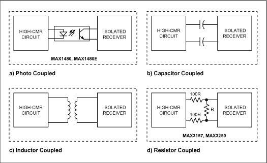
了解共模信號-Understanding Common-Mo
Abstract: To understand how common-mode signals are created and then suppressed, you should first
2009-04-29 09:35:55 1535
1535
 1535
1535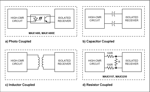
高速ADC集輸入共模范圍-High-Speed ADC Se
Abstract: The input common-mode voltage range (VCM) is important in the design of communication
2009-05-08 10:29:39 605
605
 605
605
設置高速ADC的共模輸入電壓范圍--High-Speed A
設置高速ADC的共模輸入電壓范圍--High-Speed ADC Sets Input Common-Mode Range
Abstract: The input common-mode
2009-06-09 20:41:43 1378
1378
 1378
1378
什么是CMIP (Common Management Inf
什么是CMIP (Common Management Information Protocol)
英文縮寫: CMIP (Common Management Information Protocol)
中
2010-02-22 10:45:25 563
563
 563
563什么是CCS (Common Channel Signall
什么是CCS (Common Channel Signalling)
英文縮寫: CCS (Common Channel Signalling)
中文譯名: 公共信道信令
分 類: 運營與支
2010-02-22 10:57:34 905
905
 905
905什么是CCA (Common Communication A
什么是CCA (Common Communication Adapter)
英文縮寫: CCA (Common Communication Adapter)
中文譯名: 公用通信適配器
分 類: 電
2010-02-22 10:59:20 931
931
 931
931什么是CC (Common Criteria)
什么是CC (Common Criteria)
英文縮寫: CC (Common Criteria)
中文譯名: 共同準則
分 類: 運營與支撐
解 釋:
2010-02-22 10:59:46 3160
3160
 3160
3160什么是COBOL (Common business Orie
什么是COBOL (Common business Oriented Language)
英文縮寫: COBOL (Common business Oriented Language)
中文譯名: COBOL語言
分 類:
2010-02-22 11:36:11 768
768
 768
768什么是CORBA (Common Object Reques
什么是CORBA (Common Object Request Broker Architecture)
英文縮寫: CORBA (Common Object Request Broker Architecture)
中文譯名: 通用對象請求
2010-02-22 11:48:57 883
883
 883
883共模電感Common mode Choke
共模電感簡介及應用 Common mode Choke
共模電感(Common mode Choke),也叫共模扼流圈
2010-03-10 15:20:05 9819
9819
 9819
981916位kSPS的CMOS模數轉換器AD7722
and accepts a differential input voltage range of 0 V to +2.5 V or ±1.25 V centered around a common-mode bias.
2017-09-30 15:27:55 2
2
 2
2LTC2311-12: 12-Bit + Sign, 5Msps Differential Input ADC with Wide Input Common Mode Range Data Sheet
LTC2311-12: 12-Bit + Sign, 5Msps Differential Input ADC with Wide Input Common Mode Range Data Sheet
2021-01-28 00:43:33 0
0
 0
0UG1856: Evaluating the ADRF6521 Low Frequency to 3 GHz Dual VGA with Output Common - Mode and DC Offset Control
UG1856: Evaluating the ADRF6521 Low Frequency to 3 GHz Dual VGA with Output Common - Mode and DC Offset Control
2021-01-28 11:26:15 7
7
 7
7ADRF6521: LF to 3 GHz Dual VGA with Output Common-Mode & DC Offset Control Datasheet
ADRF6521: LF to 3 GHz Dual VGA with Output Common-Mode & DC Offset Control Datasheet
2021-01-28 11:30:15 11
11
 11
11LT6018/LT1678 Demo Circuit - Low Impedance Source, High Common Mode Range Amplifier
LT6018/LT1678 Demo Circuit - Low Impedance Source, High Common Mode Range Amplifier
2021-02-20 16:04:34 8
8
 8
8AD7329:1 MSPS,8頻道,軟件選擇器,True雙極輸入,12位增益Sign Sign ADC數據Sheet
AD7329:1 MSPS,8頻道,軟件選擇器,True雙極輸入,12位增益Sign Sign ADC數據Sheet
2021-05-10 08:15:59 2
2
 2
2AD7322:2頻道,軟件選擇table,True雙極輸入,1 MSPS,12位增益Sign Sign ADC數據Sheet
AD7322:2頻道,軟件選擇table,True雙極輸入,1 MSPS,12位增益Sign Sign ADC數據Sheet
2021-05-10 11:54:17 1
1
 1
1AD7328:8頻道,軟件選擇器,True雙極輸入,12位加Sign Sign ADC數據Sheet
AD7328:8頻道,軟件選擇器,True雙極輸入,12位加Sign Sign ADC數據Sheet
2021-05-25 12:18:01 15
15
 15
15MAX44284: 36V, Input Common-Mode, High-Precision, Low-Power Current-Sense Amplifier Data Sheet MAX44284: 36V, Input Common-Mode, High-Precis
電子發燒友網為你提供ADI(ADI)MAX44284: 36V, Input Common-Mode, High-Precision, Low-Power Current-Sense
2023-10-13 18:35:03

 電子發燒友App


評論