Important considerations for infusion pump and portable medical designs
This tutorial discusses critical considerations requiring attention when designing an infusion pump, including FDA regulation, self-test circuitry for electrical leakage, and meeting the IEC 60601-1 standard for electrical medical equipment. It also provides summary coverage of pump mechanisms, power-on self-test (POST), designing for low power and portability, timekeeping, alarms, and electrostatic-discharge variables.
Overview
Computer-controlled infusion pumps represent a vast improvement in accuracy and safety over old-fashioned drip-chamber and roller-clamp systems. Modern infusion pumps provide a precisely controlled rate of fluid delivery to the patient through an intravenous (IV) line. They also include state-of-the-art safety features to ensure that any single failure of any significance is detected and reported immediately.
There are two classes of infusion pumps: large-volume pumps (LVPs) and small-volume pumps (SVPs, or syringe pumps). In an LVP, the fluids are usually contained in an IV bag or bottle, and the pump manipulates a special section of tubing between it and the patient's IV site. Some infusion pumps have the ability to control up to four IV lines to the patient, although one- and two-line versions are the most common.
Large-volume infusion pump.
Closely related to the LVP is the syringe pump. This device presses the plunger of a large syringe at a precisely controlled rate. The infusion rate of these syringe pumps is generally orders of magnitude lower than that of LVPs. Aside from the pumping mechanism, almost all other aspects of syringe pumps are similar to LVPs.
Syringe pump.
FDA-regulated medical equipment
Infusion pumps are portable medical equipment whose design and manufacture is regulated by the Food and Drug Administration (FDA). This means that their design and construction must follow precisely documented processes, and their performance must meet stringent documentation, development testing, production testing, and field maintenance requirements. The equipment also must contain comprehensive self-test and fault-indication capabilities, which require additional circuitry and the use of components that include self-test features.
Electrical leakage to the patient is a significant concern. Medical device developers must meet the requirements of the IEC 60601-1 product safety standard for electrical medical equipment. Even though the pump is a patient-connected device, the connection is nonconductive, so it falls in the least-stringent category (type B).
Given the time and expense required to achieve FDA approval, manufacturers must select a supplier with a customer-oriented discontinuance policy to ensure that system components will be available for many years.
Medical customers rely on Maxim products because over the years we have carefully avoided discontinuing parts. We realize how devastating product discontinuance can be to a customer, so we work diligently to transfer some products to newer production lines, create wafer buffers, allow last-time purchases, or develop upgrade devices. Very few Maxim parts have ever been discontinued while demand still existed. Maxim's Discontinuance Policy is one of the most flexible among our peer supplier companies.
Portability
Infusion pumps must be portable, since patients need to be mobile both within the hospital and at home. The devices must be battery powered, relatively small, and relatively lightweight. Designers, therefore, require solutions that minimize size and power consumption. Examples include the use of switching voltage regulators instead of linear regulators, even in low-energy power supplies, and the use of higher frequency switching supplies to minimize the size of external components.
Infusion pump solutions
Pump mechanism
Traditionally, stepper motors have been used in the pump mechanism to provide a precise flow rate. With angular-position sensors or Hall-effect sensors, it is possible to use DC motors instead. In these designs, the motors drive actuators (cams and fingers) to milk the tubing in precisely known fluid volumes per revolution of the mechanism.
Motor loading varies as the mechanism rotates. Motor load is affected by the position of the pump mechanism, fluid viscosity, and flow rate. To reduce power consumption, motor drive circuits can include motorload sensor signals that feed into a closed-loop control system to adjust the motor drive voltage. A variety of current-sense amplifiers, operational amplifiers, comparators, and filters are used to implement these closed-loop control systems.
Power supplies
To maximize battery life, system designers use switch-mode voltage regulators for any significant power level. Switch-mode converters should run as fast as possible to minimize size and weight. Low-dropout linear regulators (LDOs) are used only in the very lowest power circuitry where their low efficiency can be tolerated, or where the output voltage of the LDO is not much lower than the input voltage, which keeps the efficiency high.
The use of fairly sophisticated processors places requirements on power supplies that can include voltage identification digital (VID) control from the central processing unit (CPU), fast load-step response, and precision low-voltage/high-current outputs. Digital-to-analog converters (DACs) and digital potentiometers are used in these power supplies when on-the-fly programmability is needed but VID control is not built into the regulator controller.
Because these are patient-connected devices and AC-line powered, they must meet UL? and IEC safety requirements. This means that the offline switching power supply must be designed and certified by these organizations for medical applications with patient connection.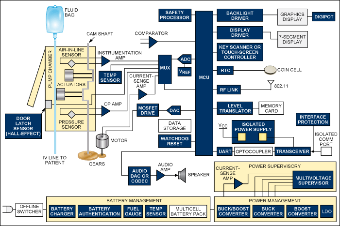
Functional block diagram of an infusion pump. For a list of Maxim's recommended solutions for infusion pumps, please visit: www.maxim-ic.com/infusion.
Battery management
Caregivers often need to transport patients while they remain on the IV, so the infusion pump must be able to operate from battery power alone for several hours. The use of rechargeable battery packs is mandatory.
The infusion pump absolutely must not run out of battery power; otherwise, it would stop pumping. Because of this, an accurate battery fuel gauge is required. Coulomb counting is the accepted method today, as voltage-sensing fuel gauges are not nearly accurate enough for this type of patient-connected equipment.
User interface
The user interface is used to program the flow rate and provides a wealth of information. In addition to the infusion rate, hospital units display parameters such as the fluid being infused, patient information, the health of the pumping system, the amount of battery life remaining, and alarm conditions.
On some wearable models intended for home use, the patient is expected to do the programming. These devices benefit from intuitive graphical user interfaces (GUIs) that guide patients through the programming process. These infusion pumps frequently have color displays and touch screens for user inputs. Visible, audible, and haptic responses to user touch inputs help designers improve the user experience. Advanced touch-screen controllers like the MAX11811 offer haptic feedback, touch processing to reduce bus traffic, and autonomous modes for precision gesture detection.
Flow rates can be programmed over a very wide range: 0.01mL/hr to 999mL/hr is typical. Due to a history of medication errors caused by pump programming errors, sophisticated software routines have been implemented in infusion pumps to warn users when unusual or dangerous infusion rates are selected.
Displays/keyboards
Full-color, high-resolution, backlit liquid-crystal displays (LCDs) are the most common. Some pumps also incorporate auxiliary alphanumeric displays. Display self-test at power-up is an FDA requirement, so designers require drivers with built-in self-test features.
Self-test and system monitoring
All infusion pumps must perform power-on self-test (POST) to meet FDA requirements. This includes tests of all critical processors, critical circuitry, indicators, displays, and alarm functionality. Some POST operations can require user observations, but additional circuitry is used for self-checking to reduce the risk of undetected failures.
For example, some models use a safety processor to monitor the performance of the main processor and to generate an alarm if unexpected behavior is detected. Another example of self-test is the simple monitoring of current through light-emitting diodes (LEDs) as they are turned on and off. If currents fall outside the acceptable range, a fault is indicated. Probably the most common self-test is the watchdog timer (WDT). Microprocessor supervisors with WDT functions are commonly used to ensure that the processor executes within proper code boundaries. In medical devices, it is usually not acceptable to have the supervisor on the same IC as the microprocessor, as this approach would subject the supervisor to the same transient errors as the microprocessor.
Supervisory functions are critical for ensuring that the pump is operating properly during patient use. Microcontrollers (of which there are often several in a single pump) must be held in reset until all power supplies are within tolerance and stable. All power supplies are monitored with voltage supervisors for undervoltage and overvoltage conditions. Motor loading is monitored and motor-stall detection is provided. (Motor stall is a critical failure causing a top-priority alarm.) Because of the criticality of the system, often power-supply voltages are monitored with ADCs so that their exact value can be recorded periodically. ADCs are also needed for sensor readings, such as temperature, motor loading, IV line pressure, and battery voltage.
Temperature sensing is implemented in the battery pack, the power supply, the motor, and the display. Due to the high efficiency of these designs, fans are usually not needed. These pumps must be splash-proof, so it is difficult to put in openings for airflow.
Alarms
Infusion pumps require audible and visible alarms to alert users to faults or potentially dangerous conditions. Bicolor or tricolor (red/orange/green) LEDs are typically used as visual indicators. Audible alarms vary from simple beepers driven by the microcontroller's pulse-width modulation (PWM) output to more sophisticated alarms (such as voice synthesis) created with an audio DAC.
Even simple audio beepers should include a self-test feature. This function can be implemented either indirectly by monitoring for a speaker impedance within range or directly by incorporating a mic near the speaker to register the audio output and confirm that it is at the proper level.
Timekeeping
Due to the criticality of patient care, every event needs to be logged and time stamped. Every key press, every start and end of an infusion, every change of configuration (pump door opening/closing, AC power disconnect, etc.), and every reported fault condition needs to be logged and time stamped for later review in case of lawsuits or instrument malfunction.
A real-time clock (RTC) is required. Since other clock sources for microprocessors and digital circuitry are not especially critical, standard crystals can be used. If extreme accuracy is needed for the RTC, Maxim has RTCs with built-in temperature-compensated crystal oscillators (TCXOs) that achieve an accuracy of ±2ppm (0°C to +40°C), which is about two orders of magnitude more accurate than a standard crystal.
Electrostatic discharge
All infusion pumps must pass IEC 61000-4-2 electrostatic discharge (ESD) requirements by either using electronics with built-in protection or by adding ESD line protectors to exposed traces. Maxim offers many interface parts with this high ESD protection built-in, as well as stand-alone ESD diode arrays.
Interfaces
Modern infusion pumps include interfaces to connect to hospital information systems. These are variously hardwired (RS-232, RS-485, USB, and Ethernet) and/or wireless interfaces (Bluetooth? and Wi-Fi?).
For wired interfaces, galvanic isolation is critical to meet the patient safety requirements of IEC 60601-1. Interfaces with unidirectional lines (such as RS-232, RS-485, RS-422) are not difficult to isolate. The only challenge is to create an isolated supply for them residing on the isolated side. An integrated device such as the MAX256 can solve this challenge by providing up to 3W of isolated power for isolated interfaces from a compact SO package.
 電子發燒友App






評論